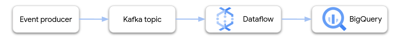
This page shows how to use Dataflow to read data from Google Cloud Managed Service for Apache Kafka and write the records to a BigQuery table. This tutorial uses the Apache Kafka to BigQuery template to create the Dataflow job.
Overview
Apache Kafka is an open source platform for streaming events. Kafka is commonly used in distributed architectures to enable communication between loosely coupled components. You can use Dataflow to read events from Kafka, process them, and write the results to a BigQuery table for further analysis.
Managed Service for Apache Kafka is a Google Cloud Platform service that helps you run secure and scalable Kafka clusters.
Required permissions
The Dataflow worker service account must have the following Identity and Access Management (IAM) roles:
- Managed Kafka Client (
roles/managedkafka.client) - BigQuery Data Editor (
roles/bigquery.dataEditor)
For more information, see Dataflow security and permissions.
Create a Kafka cluster
In this step, you create a Managed Service for Apache Kafka cluster. For more information, see Create a Managed Service for Apache Kafka cluster.
Console
Go to the Managed Service for Apache Kafka > Clusters page.
Click Create.
In the Cluster name box, enter a name for the cluster.
In the Region list, select a location for the cluster.
Click Create.
gcloud
Use the
managed-kafka clusters create
command.
gcloud managed-kafka clusters create CLUSTER \
--location=REGION \
--cpu=3 \
--memory=3GiB \
--subnets=projects/PROJECT_ID/regions/REGION/subnetworks/SUBNET_NAME
Replace the following:
CLUSTER: a name for the clusterREGION: the region where you created the subnetPROJECT_ID: your project IDSUBNET_NAME: the subnet where you want to deploy the cluster
Creating a cluster usually takes 20-30 minutes.
Create a Kafka topic
After the Managed Service for Apache Kafka cluster is created, create a topic.
Console
Go to the Managed Service for Apache Kafka > Clusters page.
Click the name of the cluster.
In the cluster details page, click Create Topic.
In the Topic name box, enter a name for the topic.
Click Create.
gcloud
Use the
managed-kafka topics create
command.
gcloud managed-kafka topics create TOPIC_NAME \
--cluster=CLUSTER \
--location=REGION \
--partitions=10 \
--replication-factor=3
Replace the following:
TOPIC_NAME: the name of the topic to create
Create a BigQuery table
In this step, you create a BigQuery table with the following schema:
| Column name | Data type |
|---|---|
name |
STRING |
customer_id |
INTEGER |
If you don't already have a BigQuery dataset, first create one. For more information, see Create datasets. Then create a new empty table:
Console
Go to the BigQuery page.
In the Explorer pane, expand your project, and then select a dataset.
In the Dataset info section, click Create table.
In the Create table from list, select Empty table.
In the Table box, enter the name of the table.
In the Schema section, click Edit as text.
Paste in the following schema definition:
name:STRING,
customer_id:INTEGER
Click Create table.
gcloud
Use the bq mk command.
bq mk --table \
  PROJECT_ID:DATASET_NAME.TABLE_NAME \
  name:STRING,customer_id:INTEGER
Replace the following:
PROJECT_ID: your project IDDATASET_NAME: the name of the datasetTABLE_NAME: the name of the table to create
Run the Dataflow job
After you create the Kafka cluster and the BigQuery table, run the Dataflow template.
Console
First, get the cluster's bootstrap server address:
In the Google Cloud console, go to the Clusters page.
Click the cluster name.
Click the Configurations tab.
Copy the bootstrap server address from Bootstrap URL.
Next, run the template to create the Dataflow job:
Go to the Dataflow > Jobs page.
Click Create job from template.
In the Job Name field, enter
kafka-to-bq.For Regional endpoint, select the region where your Managed Service for Apache Kafka cluster is located.
Select the "Kafka to BigQuery" template.
Enter the following template parameters:
- Kafka bootstrap server: the bootstrap server address
- Source Kafka topic: the name of the topic to read
- Kafka source authentication mode:
APPLICATION_DEFAULT_CREDENTIALS - Kafka message format:
JSON - Table name strategy:
SINGLE_TABLE_NAME - BigQuery output table: The BigQuery table, formatted
as follows:
PROJECT_ID:DATASET_NAME.TABLE_NAME
Under Dead letter queue, check Write errors to BigQuery.
Enter a BigQuery table name for the dead-letter queue, formatted as follows:
PROJECT_ID:DATASET_NAME.ERROR_TABLE_NAMEDon't create this table ahead of time. The pipeline creates it.
Click Run job.
gcloud
Use the
dataflow flex-template run
command.
gcloud dataflow flex-template run kafka-to-bq \
--template-file-gcs-location gs://dataflow-templates/latest/flex/Kafka_to_BigQuery \
--region LOCATION \
--parameters \
readBootstrapServerAndTopic=projects/PROJECT_ID/locations/LOCATION/clusters/CLUSTER_ID/topics/TOPIC,\
persistKafkaKey=false,\
writeMode=SINGLE_TABLE_NAME,\
kafkaReadOffset=earliest,\
kafkaReadAuthenticationMode=APPLICATION_DEFAULT_CREDENTIALS,\
messageFormat=JSON,\
outputTableSpec=PROJECT_ID:DATASET_NAME.TABLE_NAME\
useBigQueryDLQ=true,\
outputDeadletterTable=PROJECT_ID:DATASET_NAME.ERROR_TABLE_NAME
Replace the following variables:
LOCATION: the region where your Managed Service for Apache Kafka is locatedPROJECT_ID: the name of your Google Cloud Platform projectCLUSTER_ID: the of the clusterTOPIC: the name of the Kafka topicDATASET_NAME: the name of the datasetTABLE_NAME: the name of the tableERROR_TABLE_NAME: a BigQuery table name for the dead-letter queue
Don't create the table for the dead-letter queue ahead of time. The pipeline creates it.
Send messages to Kafka
After the Dataflow job starts, you can send messages to Kafka, and the pipeline writes them to BigQuery.
Create a VM in the same subnet as the Kafka cluster and install Kafka command line tools. For detailed instructions, see Set up a client machine in Publish and consume messages with the CLI.
Run the following command to write messages to the Kafka topic:
kafka-console-producer.sh \
 --topic TOPIC \
 --bootstrap-server bootstrap.CLUSTER_ID.LOCATION.managedkafka.PROJECT_ID.cloud.goog:9092 \
 --producer.config client.properties
Replace the following variables:
TOPIC: the name of the Kafka topicCLUSTER_ID: the name of the clusterLOCATION: the region where your cluster is locatedPROJECT_ID: the name of your Google Cloud Platform project
At the prompt, enter the following lines of text to send messages to Kafka:
{"name": "Alice", "customer_id": 1}
{"name": "Bob", "customer_id": 2}
{"name": "Charles", "customer_id": 3}
Use a dead-letter queue
While the job is running, the pipeline might fail to write individual messages to BigQuery. Possible errors include:
- Serialization errors, including badly-formatted JSON.
- Type conversion errors, caused by a mismatch in the table schema and the JSON data.
- Extra fields in the JSON data that are not present in the table schema.
These errors don't cause the job to fail, and they don't appear as errors in the Dataflow job log. Instead, the pipeline uses a dead letter queue to handle these types of error.
To enable the dead-letter queue when you run the template, set the following template parameters:
useBigQueryDLQ:trueoutputDeadletterTable: a fully-qualified BigQuery table name; for example,my-project:dataset1.errors
The pipeline automatically creates the table. If an error occurs when processing a Kafka message, the pipeline writes an error entry to the table.
Example error messages:
| Type of error | Event data | errorMessage |
|---|---|---|
| Serialization error | "Hello world" | Failed to serialize json to table row: "Hello world" |
| Type conversion error | {"name":"Emily","customer_id":"abc"} | { "errors" : [ { "debugInfo" : "", "location" : "age", "message" : "Cannot convert value to integer (bad value): abc", "reason" : "invalid" } ], "index" : 0 } |
| Unknown field | {"name":"Zoe","age":34} | { "errors" : [ { "debugInfo" : "", "location" : "age", "message" : "no such field: customer_id.", "reason" : "invalid" } ], "index" : 0 } |
Work with BigQuery data types
Internally, the Kafka I/O connector converts JSON message payloads to
Apache Beam TableRow objects, and translates the TableRow
field values into BigQuery types.
The following table shows JSON representations of BigQuery data types.
| BigQuery type | JSON representation |
|---|---|
ARRAY |
[1.2,3] |
BOOL |
true |
DATE |
"2022-07-01" |
DATETIME |
"2022-07-01 12:00:00.00" |
DECIMAL |
5.2E11 |
FLOAT64 |
3.142 |
GEOGRAPHY |
"POINT(1 2)"Specify the geography using either well-known text (WKT) or GeoJSON, formatted as a string. For more information, see Loading geospatial data. |
INT64 |
10 |
INTERVAL |
"0-13 370 48:61:61" |
STRING |
"string_val" |
TIMESTAMP |
"2022-07-01T12:00:00.00Z"Use the JavaScript |
Structured data
If your JSON messages follow a consistent schema, you can represent JSON objects
by using the
STRUCT data
type in BigQuery.
In the following example, the answers field is a JSON object with two
subfields, a and b:
{"name":"Emily","answers":{"a":"yes","b":"no"}}
The following SQL statement creates a BigQuery table with a compatible schema:
CREATE TABLE my_dataset.kafka_events (name STRING, answers STRUCT<a STRING, b STRING>);
The resulting table looks like the following:
+-------+----------------------+
| name  |       answers        |
+-------+----------------------+
| Emily | {"a":"yes","b":"no"} |
+-------+----------------------+
Semi-structured data
If your JSON messages don't follow a strict schema, consider storing them in
BigQuery as a
JSON data type.
By storing JSON data as a JSON type, you don't need to define the schema
upfront. After data ingestion, you can query the data by using the field access
(dot notation) and array access operators in GoogleSQL. For more
information, see
Working with JSON data in GoogleSQL.
Use a UDF to transform the data
This tutorial assumes that the Kafka messages are formatted as JSON, and that the BigQuery table schema matches the JSON data, with no transformations applied to the data.
Optionally, you can provide a JavaScript user-defined function (UDF) that transforms the data before it is written to BigQuery. The UDF can also perform additional processing, such as filtering, removing personal identifiable information (PII), or enriching the data with additional fields.
For more information, see Create user-defined functions for Dataflow templates.