This tutorial introduces a ready-to-use solution that uses Google Distributed Cloud and Config Management to deploy Kubernetes clusters on the edge at scale. This tutorial is for platform operators and developers. You should have familiarity with the following technologies and concepts:
- Ansible playbooks.
- Edge deployments and their challenges.
- How to work with a Google Cloud project.
- Deploying a containerized web application.
gcloudandkubectlcommand-line interfaces.
In this tutorial you use Compute Engine virtual machines (VMs) to emulate nodes deployed on the edge, and a sample point-of-sale application as the edge workload. Google Distributed Cloud and Config Management provide centralized management and control for your edge cluster. Config Management dynamically pulls new configs from GitHub and applies these policies and configs to your clusters.
Edge deployment architecture
A retail edge deployment is a good way to illustrate the architecture that's used in a typical Google Distributed Cloud deployment.
A physical retail store is the closest point of interaction between an enterprise business unit and the consumer. Software systems inside stores must run their workloads, receive timely updates, and report critical metrics in isolation from the enterprise's central management system. Furthermore, these software systems need to be designed so that they can be expanded to more store locations in the future. While Google Distributed Cloud satisfies all these requirements for store software systems, the edge profile enables an important use case: deployments in environments with limited hardware resources like a retail store front.
The following diagram shows an Google Distributed Cloud deployment that uses the edge profile in a retail store:
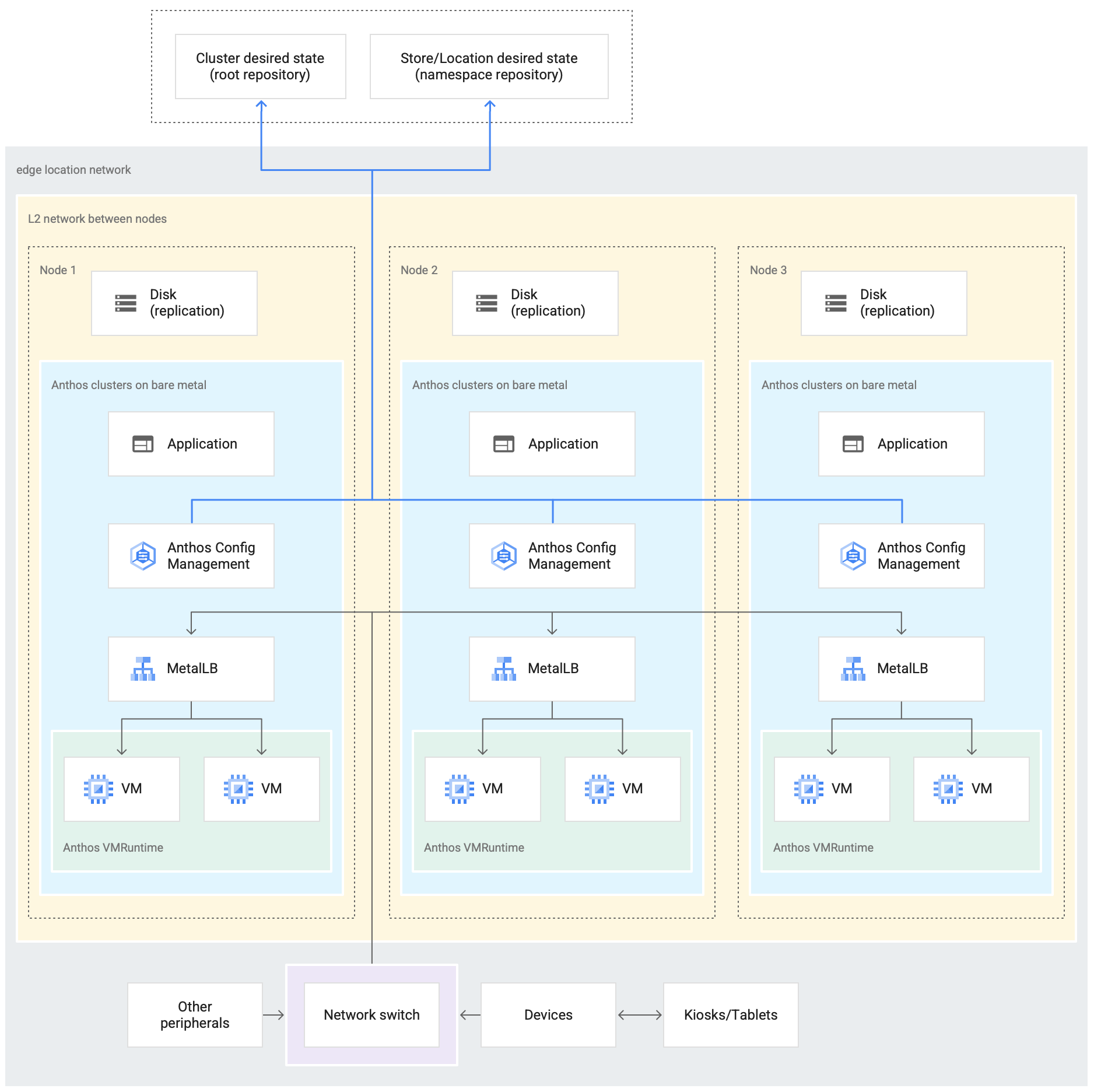
The preceding diagram shows a typical physical retail store. The store has smart
devices like card readers, point-of-sale machines, cameras, and printers.
The store also has three physical computing hardware devices (labeled Node 1, Node 2 and Node 3).
All these devices are connected to a central network switch. Thus, the three
computing devices are connected to each other through a Layer 2 network. The
computing devices networked together make up the bare metal infrastructure.
Google Distributed Cloud is running inside each of the three computing devices. These
devices also have their own disk storage and are configured for data replication
between them for high availability.
The diagram also shows the following key components that are part of a Google Distributed Cloud deployment:
- The component marked as MetalLB is the bundled load balancer that's deployed with Google Distributed Cloud.
- The Config Management component enables synchronizing the state of the cluster against source repositories. It is a highly recommended optional add-on that requires separate installation and configuration. For more information on how to set up Config Management and the different nomenclature, see the Config Management documentation.
The root repository and namespace repository shown at the top of the diagram outside the store location represent two source repositories.
Changes to the cluster are pushed to these central source repositories. Google Distributed Cloud deployments in various edge locations pull updates from the source repositories. This behavior is represented by the arrows connecting the two repositories in the diagram to the Config Management components inside the Google Distributed Cloud cluster running in the devices.
Another key component that's depicted as part of the cluster is the VM Runtime on Google Distributed Cloud. VM Runtime on Google Distributed Cloud enables running existing VM-based workloads inside the cluster without the need for containerization. The VM Runtime on Google Distributed Cloud documentation explains how to enable it and deploy your VM workloads into the cluster.
The component marked as Application denotes software deployed into the cluster by the retail store. The point of sale application seen in the kiosks of a retail store could be one example of such an application.
The boxes at the bottom of the diagram represent the many devices (like kiosks, tablets, or cameras) inside a retail store, all of which are connected to a central network switch. The local networking inside the store enables the applications running inside the Google Distributed Cloud deployment to reach these devices.
In the next section, you see the emulation of this retail store deployment in Google Cloud using Compute Engine VMs. This emulation is what you use in the tutorial that follows to experiment with Google Distributed Cloud.
Emulated edge deployment in Google Cloud
The following diagram is a depiction of everything that you set up in Google Cloud in this tutorial. This diagram correlates to the retail store diagram from the preceding section. This deployment represents an emulated edge location in which the point of sale application is deployed. The architecture also shows a simple point of sale sample application workload that you use in this tutorial. You access the point of sale application inside the cluster by using a web browser as a kiosk.
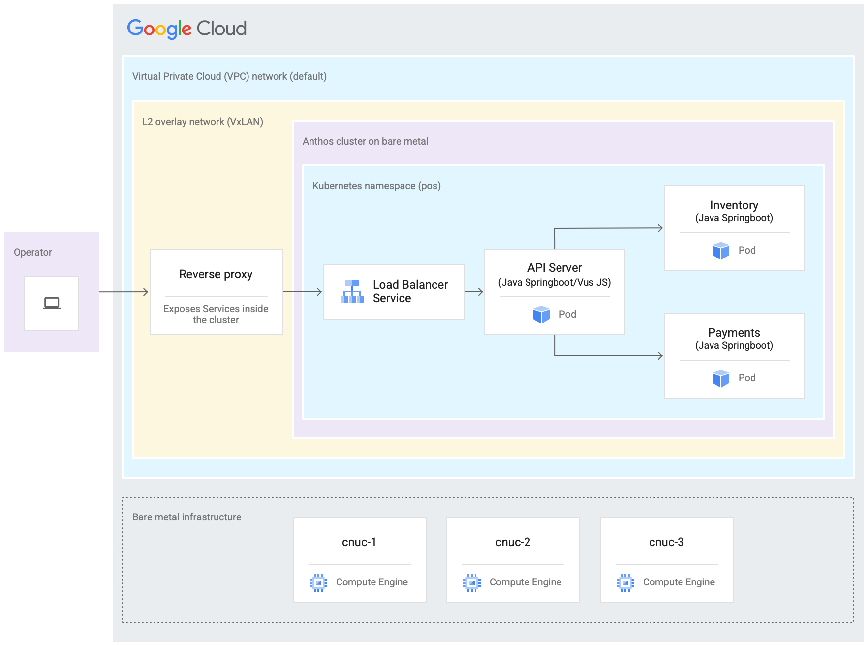
The three Compute Engine virtual machines (VMs) in the preceding diagram represent the physical hardware (or nodes) in a typical edge location. This hardware would be connected together with network switches to make up the bare metal infrastructure. In our emulated environment in Google Cloud, these VMs are connected to each other through the default Virtual Private Cloud (VPC) network in the Google Cloud project.
In a typical Google Distributed Cloud installation you can configure your own load balancers. However, for this tutorial you don't set up an external load balancer. Instead you use the bundled MetalLB load balancer that's installed with Google Distributed Cloud. The bundled MetalLB load balancer requires Layer 2 network connectivity between the nodes. Thus, Layer 2 connectivity between the Compute Engine VMs is enabled by creating a VxLAN overlay network on top of the default Virtual Private Cloud (VPC) network.
Within the rectangle labeled "L2 overlay network (VxLAN)" the software components running inside the three Compute Engine VMs are shown. This rectangle includes the Google Distributed Cloud cluster and a Reverse proxy. The cluster is represented by the "Google Distributed Cloud" rectangle. THis rectangle representing the cluster includes another rectangle marked as "Kubernetes namespace (pos)". This represents a Kubernetes namespace inside the cluster. All the components inside this Kubernetes namespace make up the point of sale application that is deployed into the Anthos cluster. The point of sale application has three microservices: API Server, Inventory and Payments. All these components together represent one "application" shown in the earlier Edge rollout architecture diagram.
The Anthos cluster's bundled MetalLB load balancer can't be directly reached from outside the VMs. The diagram shows an NGINX reverse proxy being configured to run inside the VMs to route traffic coming into the Compute Engine VMs to the load balancer. This is only a workaround for the purposes of this tutorial where the edge nodes are emulated using Google Cloud Compute Engine VMs. In a real edge location this can be done with proper network configuration.
Objectives
- Use Compute Engine VMs to emulate a bare metal infrastructure that runs in an edge location.
- Create an Google Distributed Cloud cluster in the emulated edge infrastructure.
- Connect and register the cluster with Google Cloud.
- Deploy a sample point-of-sale application workload on the Anthos cluster.
- Use the Google Cloud console to verify and monitor the point-of-sale application that operates on the edge location.
- Use Config Management to update the point-of-sale application that runs on the Anthos cluster.
Before you begin
In the Google Cloud console, on the project selector page, select or create a Google Cloud project.
Make sure that billing is enabled for your Cloud project. Learn how to check if billing is enabled on a project.
Install and initialize the Google Cloud CLI.
Fork and clone the anthos-samples repository
All the scripts used in this tutorial are stored in the anthos-samples
repository. The folder structure under
/anthos-bm-edge-deployment/acm-config-sink
is organized according to what is expected by Config Management.
Clone this repository to your own GitHub account before you continue with the
following steps.
If you don't have one already, create an account on GitHub.
Create a personal access token to use in the Config Management configuration. This is required for the Config Management components in the cluster to authenticate with your GitHub account when trying to synchronize new changes.
- Select the
public_reposcope only. - Save the access token you created in a safe place to use later.
- Select the
Fork the
anthos-samplesrepository to your own GitHub account:- Go to the anthos-samples repository.
- Click on the Fork icon on the top-right corner of the page.
- Click on the GitHub user account you want to fork the repository to. You are automatically redirected to the page with your forked version of the anthos-samples repository.
Open a terminal in your local environment.
Clone the forked repository by running the following command, where GITHUB_USERNAME is the username for your GitHub account:
git clone https://github.com/GITHUB_USERNAME/anthos-samples
cd anthos-samples/anthos-bm-edge-deployment
Set up the workstation environment
To complete the edge deployment described in this document, you need one workstation with access to the Internet and the following tools installed:
- Docker
- envsubst command-line interface tool (usually pre-installed on Linux and other Unix-like OSes)
Run all of the commands in the tutorial on the workstation you configure in this section.
On your workstation, initialize the environment variables in a new shell instance:
export PROJECT_ID="PROJECT_ID"
export REGION="us-central1"
export ZONE="us-central1-a"

# port on the admin Compute Engine instance you use to set up an nginx proxy
# this allows to reach the workloads inside the cluster via the VM IP
export PROXY_PORT="8082"

# should be a multiple of 3 since N/3 clusters are created with each having 3 nodes
export GCE_COUNT="3"

# url to the fork of: https://github.com/GoogleCloudPlatform/anthos-samples
export ROOT_REPO_URL="https://github.com/GITHUB_USERNAME/anthos-samples"

# this is the username used to authenticate to your fork of this repository
export SCM_TOKEN_USER="GITHUB_USERNAME"

# access token created in the earlier step
export SCM_TOKEN_TOKEN="ACCESS_TOKEN"
Replace the following values:
- PROJECT_ID: your Google Cloud project ID.
- GITHUB_USERNAME: your GitHub username.
- ACCESS_TOKEN: the personal access token you created for your GitHub repository.
Keep the default values for the other environment variables. They are explained in the sections that follow.
On your workstation, initialize Google Cloud CLI:
gcloud config set project "${PROJECT_ID}" gcloud services enable compute.googleapis.com gcloud config set compute/region "${REGION}" gcloud config set compute/zone "${ZONE}"On your workstation, create the Google Cloud service account for the Compute Engine instances. This script creates the JSON key file for the new service account at
<REPO_ROOT>/anthos-bm-edge-deployment/build-artifacts/consumer-edge-gsa.json. It also sets up the Cloud Key Management Service keyring and key for SSH private key encryption../scripts/create-primary-gsa.shA portion of the script is visible below. Click on the
View on GitHublink to see the entire script.
Provision the Compute Engine instances
In this section, you create the Compute Engine VMs where Google Distributed Cloud will be installed. You also verify connectivity to these VMs before proceeding to the install section.
On your workstation, create SSH keys that are used for communication between the Compute Engine instances.
ssh-keygen -f ./build-artifacts/consumer-edge-machineEncrypt the SSH private key using Cloud Key Management Service.
gcloud kms encrypt \
    --key gdc-ssh-key \
    --keyring gdc-ce-keyring \
    --location global \
    --plaintext-file build-artifacts/consumer-edge-machine \
    --ciphertext-file build-artifacts/consumer-edge-machine.encrypted
Generate the environment configuration file
.envrcand source it. After created inspect the.envrcfile to ensure that the environment variables have been replaced with the correct values.envsubst < templates/envrc-template.sh > .envrc source .envrcThe following is an example of an
.envrcfile generated by replacing the environment variables in thetemplates/envrc-template.shfile. Notice that the lines that were updated are highlighted:Create Compute Engine instances where Google Distributed Cloud is installed.
./scripts/cloud/create-cloud-gce-baseline.sh -c "$GCE_COUNT" | \
    tee ./build-artifacts/gce-info
Install Google Distributed Cloud with Ansible
The script used in this guide creates Google Distributed Cloud clusters in
groups of three Compute Engine instances. The number of clusters created is
controlled by the GCE_COUNT environment variable. For example, you set the
environment variable GCE_COUNT to 6 to create two
Google Distributed Cloud clusters with 3 VM instances each. By default
the GCE_COUNT environment variable is set to 3. Thus, in this guide one
cluster with 3 Compute Engine instances will be created. The VM
instances are named with a prefix cnuc- followed by a number. The first VM
instance of each cluster acts as the admin workstation from which the
installation is triggered. The cluster is also given the same name as the admin
workstation VM (for example, cnuc-1, cnuc-4, cnuc-7).
The Ansible playbook does the following:
- Configures the Compute Engine instances with the necessary tools, such
as
docker,bmctl,gcloud, andnomos. - Installs Google Distributed Cloud in the configured Compute Engine instances.
- Creates an Google Distributed Cloud standalone cluster called
cnuc-1. - Registers the
cnuc-1cluster with Google Cloud. - Installs Config Management into the
cnuc-1cluster. - Configures Config Management to sync with the cluster
configurations located at
anthos-bm-edge-deployment/acm-config-sinkin your forked repository. - Generates the
Login tokenfor the cluster.
Complete the following steps to set up and start the installation process:
On your workstation, create the Docker image used for the installation. This image has all the tools required for the installation process, such as Ansible, Python, and Google Cloud CLI.
gcloud builds submit --config docker-build/cloudbuild.yaml docker-build/When the build runs successfully, it produces an output like the following:
...
latest: digest: sha256:99ded20d221a0b2bcd8edf3372c8b1f85d6c1737988b240dd28ea1291f8b151a size: 4498
DONE
----------------------------------------------------------------------------------------------------------------------------------------------------------------------------------
ID                                    CREATE_TIME                DURATION  SOURCE                                                                                         IMAGES                                                  STATUS
2238baa2-1f41-440e-a157-c65900b7666b  2022-08-17T19:28:57+00:00  6M53S     gs://my_project_cloudbuild/source/1660764535.808019-69238d8c870044f0b4b2bde77a16111d.tgz  gcr.io/my_project/consumer-edge-install (+1 more)  SUCCESS
Generate the Ansible inventory file from template.
envsubst < templates/inventory-cloud-example.yaml > inventory/gcp.yamlRun the installation script that starts a Docker container from the image built previously. The script internally uses Docker to spawn the container with a volume mount to the current working directory. Upon successful completion of this script you must be inside the Docker container that was created. You trigger the Ansible installation from inside this container.
./install.shWhen the script runs successfully, it produces an output like the following:
...
Check the values above and if correct, do you want to proceed? (y/N): y
Starting the installation
Pulling docker install image...

==============================
Starting the docker container. You will need to run the following 2 commands (cut-copy-paste)
==============================
1: ./scripts/health-check.sh
2: ansible-playbook all-full-install.yaml -i inventory
3: Type 'exit' to exit the Docker shell after installation
==============================
Thank you for using the quick helper script!
(you are now inside the Docker shell)
From inside the Docker container, verify access to the Compute Engine instances.
./scripts/health-check.shWhen the script runs successfully, it produces an output like the following:
...
cnuc-2 | SUCCESS => {"ansible_facts": {"discovered_interpreter_python": "/usr/bin/python3"},"changed": false,"ping": "pong"}
cnuc-3 | SUCCESS => {"ansible_facts": {"discovered_interpreter_python": "/usr/bin/python3"},"changed": false,"ping": "pong"}
cnuc-1 | SUCCESS => {"ansible_facts": {"discovered_interpreter_python": "/usr/bin/python3"},"changed": false,"ping": "pong"}
From inside the Docker container, run the Ansible playbook for installing Google Distributed Cloud on Compute Engine instances. Upon completion you will see the
Login Tokenfor the cluster printed on screen.ansible-playbook all-full-install.yaml -i inventory | tee ./build-artifacts/ansible-run.logWhen the install runs successfully, it produces an output like the following:
...
TASK [abm-login-token : Display login token] **************************************************************************
ok: [cnuc-1] => {
    "msg": "eyJhbGciOiJSUzI1NiIsImtpZCI6Imk2X3duZ3BzckQyWmszb09sZHFMN0FoWU9mV1kzOWNGZzMyb0x2WlMyalkifQ.eymljZS1hY2NvdW
iZXJuZXRlcy5pby9zZXJ2aWNlYWNjb3VudC9zZWNyZXQubmFtZSI6ImVkZ2Etc2EtdG9rZW4tc2R4MmQiLCJrdWJlcm5ldGVzLmlvL3NlcnZpY2VhY2Nvd
4CwanGlof6s-fbu8"
}
skipping: [cnuc-2]
skipping: [cnuc-3]

PLAY RECAP ***********************************************************************************************************
cnuc-1                     : ok=205  changed=156  unreachable=0    failed=0    skipped=48   rescued=0    ignored=12
cnuc-2                     : ok=128  changed=99   unreachable=0    failed=0    skipped=108  rescued=0    ignored=2
cnuc-3                     : ok=128  changed=99   unreachable=0    failed=0    skipped=108  rescued=0    ignored=2
Log in to the Google Distributed Cloud cluster in the Google Cloud console
After the Ansible playbook runs to completion, a standalone Google Distributed Cloud cluster is installed inside the Compute Engine VMs. This cluster is also registered to Google Cloud via the Connect Agent. However, to see details about this cluster you have to log into the cluster from the Google Cloud console. To login to the GKE cluster complete the following steps.
Copy the token from the output of the Ansible playbook in the previous section.
In the Google Cloud console, go to the Kubernetes clusters page and use the copied token to log in to the
cnuc-1cluster.Go to the Kubernetes clusters page
- In the list of clusters, click
Actions
next to the
cnuc-1cluster, and then click Log in. - Select Token and paste in the copied token.
- Click Login.
- In the list of clusters, click
Actions
next to the
In the Google Cloud console, go to the Config Management page to check the Config spec status. Verify that the status is Synced. A status of Synched indicates that Config Management has successfully synchronized your GitHub configs with your deployed cluster,
cnuc-1.Go to the Config Management page

Configure a proxy for external traffic
The Google Distributed Cloud cluster installed in the previous steps uses a
bundled load balancer called MetalLB.
This load balancer service is accessible only through a
Virtual Private Cloud (VPC) IP address. To route traffic coming in through its
external IP to the bundled load balancer, set up a reverse proxy service in the
admin host (cnuc-1). This reverse proxy service allows you to reach the API
Server of the point of sale application through the external IP of the admin
host (cnuc-1).
The installation scripts in the earlier steps installed NGINX in the admin hosts along with a sample configuration file. Update this file to use the IP address of the load balancer service and restart NGINX.
On your workstation, use SSH to log into the admin workstation:
ssh -F ./build-artifacts/ssh-config abm-admin@cnuc-1From inside the admin workstation, set up NGINX reverse proxy to route traffic to the API Server Load balancer service. Get the IP address of the Load balancer type Kubernetes service:
ABM_INTERNAL_IP=$(kubectl get services api-server-lb -n pos | awk '{print $4}' | tail -n 1)Update the template configuration file with the fetched IP address:
sudo sh -c "sed 's/<K8_LB_IP>/${ABM_INTERNAL_IP}/g' \
    /etc/nginx/nginx.conf.template > /etc/nginx/nginx.conf"
Restart NGINX to make sure that the new configuration is applied:
sudo systemctl restart nginxCheck and verify the status of the NGINX server to reports "active (running)":
sudo systemctl status nginxWhen NGINX is running successfully, it produces an output like the following example:
● nginx.service - A high performance web server and a reverse proxy server
    Loaded: loaded (/lib/systemd/system/nginx.service; enabled; vendor preset: enabled)
    Active: active (running) since Fri 2021-09-17 02:41:01 UTC; 2s ago
    Docs: man:nginx(8)
    Process: 92571 ExecStartPre=/usr/sbin/nginx -t -q -g daemon on; master_process on; (code=exited, status=0/SUCCESS)
    Process: 92572 ExecStart=/usr/sbin/nginx -g daemon on; master_process on; (code=exited, status=0/SUCCESS)
Main PID: 92573 (nginx)
    Tasks: 17 (limit: 72331)
    Memory: 13.2M
    CGroup: /system.slice/nginx.service
            ├─92573 nginx: master process /usr/sbin/nginx -g daemon on; master_process on;
            ├─92574 nginx: worker process
            ├─92575 nginx: worker process
            ├─92577 nginx: ....
            ...
            ...
Exit from the SSH session into the admin workstation:
exitExit from the shell session into the Docker container. Upon exiting the admin instance, you are still inside the Docker container used for the installation:
exit
Access the point of sale application
With the external proxy setup you are able to access the application running inside the GKE cluster. To access the sample point of sale application, complete the following steps.
On your workstation, get the external IP address of the admin Compute Engine instance and access the UI of the point of sale application:
EXTERNAL_IP=$(gcloud compute instances list \
    --project ${PROJECT_ID} \
    --filter="name:cnuc-1" \
    --format="get(networkInterfaces[0].accessConfigs[0].natIP)")
echo "Point the browser to: ${EXTERNAL_IP}:${PROXY_PORT}"
When the scripts run successfully, they produce output like the following:
Point the browser to: 34.134.194.84:8082Open your web browser and navigate to the IP address shown in the output of the previous command. You can access and test the sample point of sale application, as shown in the following example screenshot:
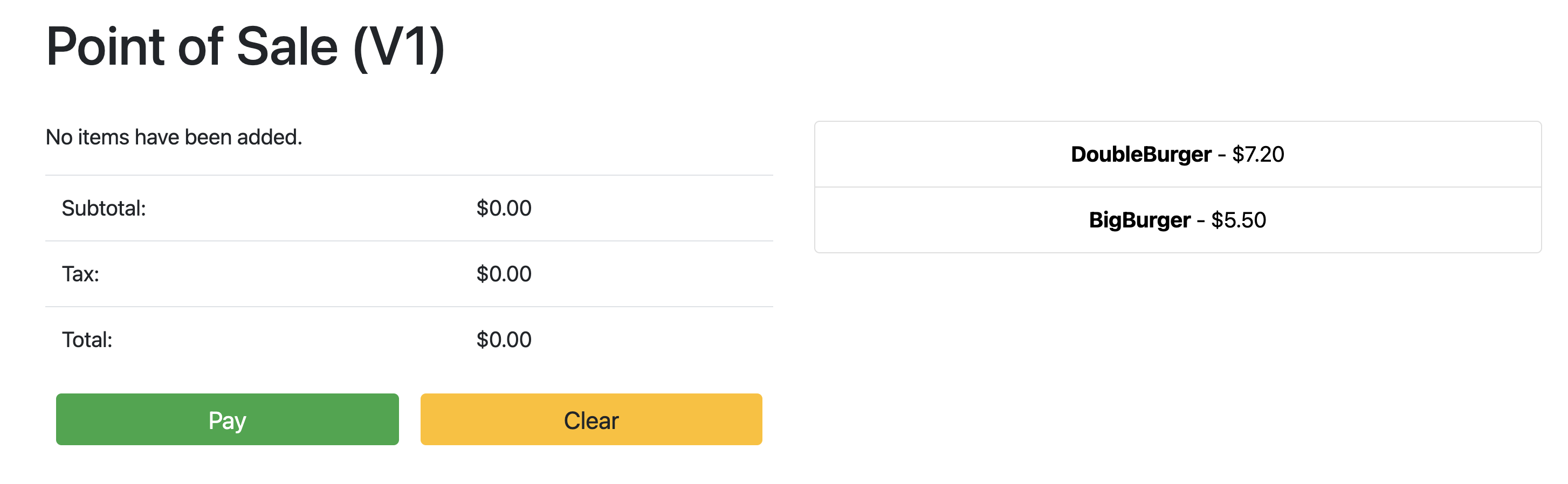
Use Config Management to update the API Server
The sample application can be upgraded to a newer version by updating the
configuration files in the root repository. Config Management detects
the updates and automatically makes the changes to your cluster. In this example
the root repository is the anthos-samples repository that you cloned at the
beginning of this guide. To see how the sample point of sale application can go
through an upgrade deployment to a newer version, complete the following steps.
On your workstation, update the
imagefield to change the API Server version fromv1tov2. The YAML configuration for the deployment is in the file atanthos-bm-edge-deployment/acm-config-sink/namespaces/pos/api-server.yaml.Add, commit, and push the changes to your forked repository:
git add acm-config-sink/namespaces/pos/api-server.yaml
git commit -m "chore: updated api-server version to v2"
git push
In the Google Cloud console, go to the Config Management page to check the Config spec status. Verify that the status is Synced.
In the Google Cloud console, go to the Kubernetes Engine Workloads page to verify that the Deployment is updated.
When the status of the Deployment is OK, point your browser to the IP address from the previous section to view the point of sale application. Note that the version in the title shows "V2", indicating that your application change was deployed, as shown in the following example screenshot:
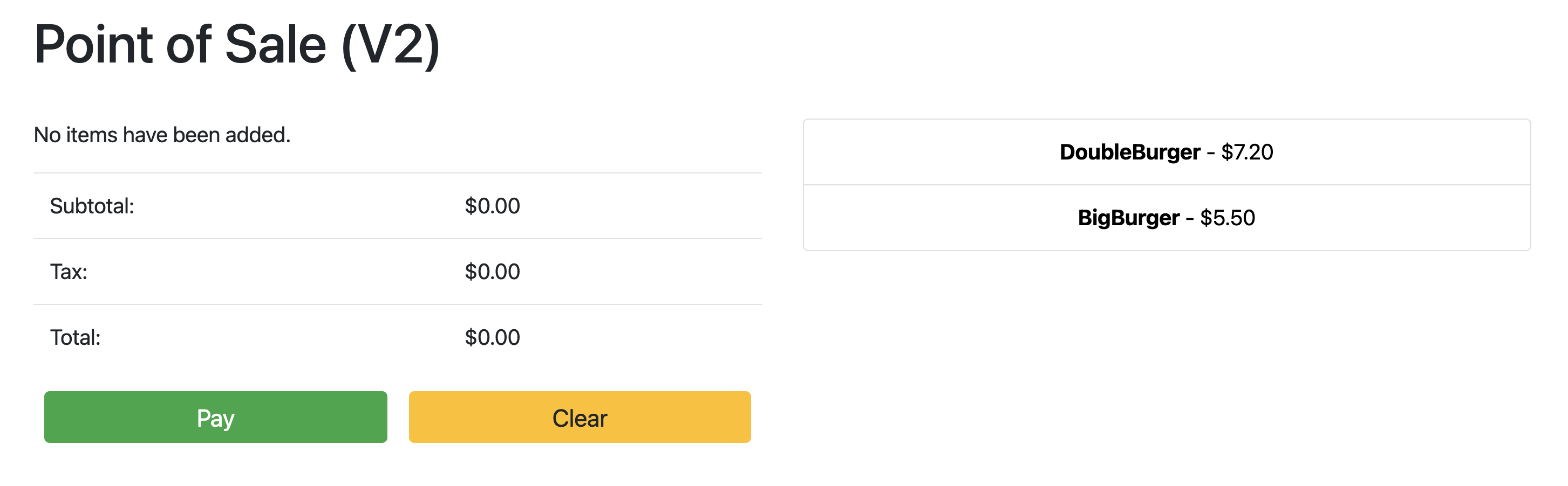
You might have to do a hard refresh of the browser tab to see the changes.
Clean up
To avoid unnecessary Google Cloud charges, delete the resources used for this guide when you are done with it. You can either delete these resources manually, or delete your Google Cloud project, which also gets rid of all resources. In addition, you might also want to clean up the changes made in your local workstation:
Local workstation
The following files have to be updated to clear changes made by the
installation scripts.
- Remove the Compute Engine VM IP addresses added to the
/etc/hostsfile. - Remove the SSH configuration for
cnuc-*in the~/.ssh/configfile. - Remove the Compute Engine VM fingerprints from the
~/.ssh/known_hostsfile.
Delete Project
If you created a dedicated project for this procedure, delete the Google Cloud project
from the Google Cloud console.
Manual
If you used an existing project for this procedure, do the following:
- Unregister all Kubernetes clusters with a name prefixed by
cnuc-. - Delete all Compute Engine VMs with a name prefixed by
cnuc-. - Delete the Cloud Storage bucket with a name prefixed by
abm-edge-boot. - Delete the Firewall Rules
allow-pod-ingressandallow-pod-egress. - Delete the Secret Manager secret
install-pub-key.
What's next?
You can expand on this guide by adding another edge location. Setting the
GCE_COUNT environment variable to 6 and re-running the same steps from
the preceding sections creates three new Compute Engine instances
(cnuc-4, cnuc-5, cnuc-6) and a new Google Distributed Cloud
standalone cluster called cnuc-4.
You can also try updating the cluster configurations
in your forked repository to selectively apply different versions of the
point of sale application to the two clusters, cnuc-1 and cnuc-4, using
ClusterSelectors.
For details about the individual steps in this guide, the scripts involved, see the anthos-samples repository.