This document describes how to set up and use bundled load balancers with Border
Gateway Protocol (BGP) for Google Distributed Cloud. This load-balancing mode
supports the advertisement of ServiceType LoadBalancer virtual IP addresses
(VIPs) through external Border Gateway Protocol (eBGP) for your clusters. In
this scenario, your cluster network is an autonomous system, which interconnects
with another autonomous system, an external network, through peering.
The bundled load balancers with BGP capability apply to all cluster types, but admin clusters only support the control plane load-balancing partof this capability.
Using the bundled load balancers with BGP feature provides the following benefits:
- Uses N-way active/active load-balancing capability, providing faster failover and more efficient utilization of available bandwidth.
- Supports Layer 3 protocol that interoperates with third-party top-of-rack (ToR) switches and routers that are compatible with eBGP.
- Enables data centers that are running an advanced software defined networking (SDN) stack to push the Layer 3 boundary all the way to the clusters.
How bundled load balancing with BGP works
The following sections provide a quick summary of how bundled load balancers with BGP work.
BGP peering
The bundled load balancers with BGP feature starts several BGP connections to your infrastructure. BGP has the following technical requirements:
- Peering sessions are separate for control plane VIP and for service VIPs.
- Control plane peering sessions are initiated from the IP addresses of the control plane nodes'.
- Service peering sessions are initiated from floating IP addresses that you
specify in the
AnthosNetworkGatewaycustom resource. - Anthos Network Gateway controller manages the floating IP addresses.
- Bundled BGP-based load balancing supports eBGP peering only.
- Multi-hop peering is supported by default.
- MD5 passwords on BGP sessions are not supported.
- IPv6-based peering sessions are not supported.
- Routes advertised to any peer are expected to be redistributed throughout the network and reachable from anywhere else in the cluster.
- Use of BGP
ADD-PATHcapability in receive mode is strongly recommended for peering sessions. - Advertising multiple paths from each peer results in active/active load balancing.
- Equal-cost multipath routing (ECMP) should be enabled for your network so that multiple paths can be used to spread traffic across a set of load balancer nodes.
Control plane load balancing
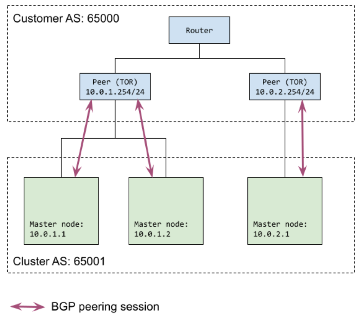
Each control plane node in your cluster establishes BGP sessions with one or more peers in your infrastructure. We require that each control plane node has at least one peer. In the cluster configuration file, you can configure which control plane nodes connect to which external peers.
The following diagram shows an example of control plane peering. The cluster has two control plane nodes in one subnet and one in another. There is an external peer (TOR) in each subnet and the Google Distributed Cloud control plane nodes peer with their TOR.
Service load balancing
In addition to the peering sessions that are initiated from each control plane
node for the control plane peering, additional peering sessions are initiated for
LoadBalancer Services. These peering sessions are not initiated from cluster
node IPs directly, instead they use floating IPs.
Services with an externalTrafficPolicy=Local network policy are not supported.
Floating IP addresses
Service load balancing requires you to reserve floating IP addresses in the
cluster node subnets to use for BGP peering. At least one floating IP address
is required for the cluster, but we recommend you reserve at least two addresses
to ensure high availability for BGP sessions. The floating IP addresses are
specified in the AnthosNetworkGateway custom resource (CR), which can be
included in the cluster configuration file.
Floating IP addresses remove the worry about mapping BGP speaker IP
addresses to nodes. The Anthos Network Gateway controller takes care of
assigning the AnthosNetworkGateway to nodes and also manages the floating IP
addresses. If a node goes down, the Anthos Network Gateway controller reassigns
floating IP addresses to ensure that external peers have a deterministic IP
address to peer with.
External peers
You specify the external peers used for peering sessions with the floating IP
addresses in the BGPLoadBalancer custom resource, which you add to the
cluster configuration file. The external peers can be the same as were specified
for control plane peering in the loadBalancer.controlPlaneBGP section of the
cluster configuration file, or you can specify different peers.
The Anthos Network Gateway controller attempts to establish two sessions to each
external peer from the set of reserved the floating IP addresses. We recommend
that you specify at least two external peers to ensure high availability for BGP
sessions. Each external peer designated for Services load balancing must be
configured to peer with every floating IP address specified in the
AnthosNetworkGateway custom resource.
Load balancer nodes
A subset of nodes from the cluster is used for load balancing, which means they
are the nodes advertised to be able to accept incoming load-balancing traffic.
This set of nodes defaults to the control plane node pool, but you can specify a
different node pool in the loadBalancer section of the cluster configuration
file. If you specify a node pool, it is used for the load balancer nodes,
instead of the control plane node pool.
The floating IP addresses, which function as BGP speakers, may or may not run on the load balancer nodes. The floating IP addresses are assigned to a node in the same subnet and peering is initiated from there, regardless of whether it is a load balancer node. However, next hops advertised over BGP are always the load balancer nodes.
Example peering topology
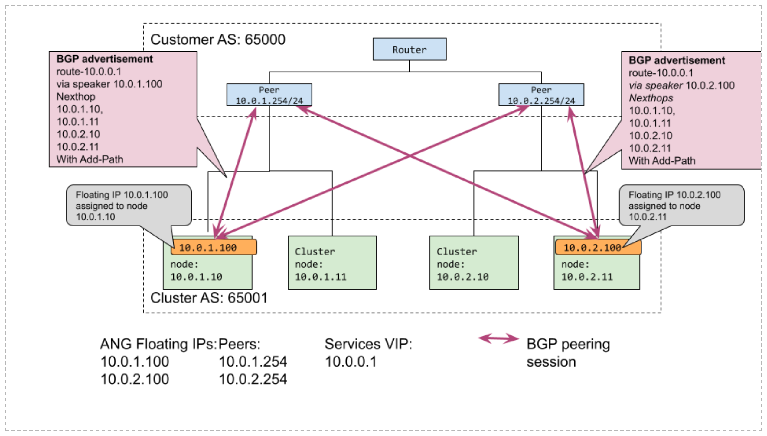
The following diagram shows an example of Service load balancing with BGP peering. There are two floating IP addresses assigned to nodes in their respective subnets. There are two external peers defined. Each floating IP peers with both external peers.
Set up the BGP load balancer
The following sections describe how to configure your clusters and your external network to use the bundled load balancer with BGP.
Plan your integration with external infrastructure
In order to use the bundled load balancer with BGP, you need to set up the external infrastructure:
External infrastructure must be configured to peer with each of the control plane nodes in the cluster to set up the control plane communication. These peering sessions are used to advertise the Kubernetes control plane VIPs.
External infrastructure must be configured to peer with a set of reserved floating IP addresses for data plane communication. The floating IP addresses are used for BGP peering for the Service VIPs. We recommend you use two floating IP addresses and two peers to ensure high availability for BGP sessions. The process of reserving floating IP is described as part of configuring your cluster for bundled load balancing with BGP.
When you have configured the infrastructure, add the BGP peering information to the cluster configuration file. The cluster you create can initiate peering sessions with the external infrastructure.
Configure your cluster for bundled load balancing with BGP
You enable and configure bundled load balancing with BGP in the cluster configuration file when you create a cluster.
Add the
baremetal.cluster.gke.io/enable-anthos-network-gatewayannotation to the cluster configuration file and set it totrue.This annotation enables the Anthos Network Gateway controller.
apiVersion: baremetal.cluster.gke.io/v1
kind: Cluster
metadata:
  name: bm
  namespace: cluster-bm
  # This annotation is required for BGP load balancer
  annotations:
    baremetal.cluster.gke.io/enable-anthos-network-gateway: "true"
spec:
...
In the
loadBalancersection of the cluster configuration file, setmodetobundledand add atypefield with a value ofbgp.These field values enable BGP-based bundled load balancing.
...
  loadBalancer:
    mode: bundled

    # type can be 'bgp' or 'layer2'. If no type is specified, we default to layer2.
    type: bgp
    ...
To specify the BGP-peering information for the control plane, add the following fields to the
loadBalancersection:... # AS number for the cluster localASN: CLUSTER_ASN # List of BGP peers used for the control plane peering sessions. bgpPeers: - ip: PEER_IP asn: PEER_ASN # optional; if not specified, all CP nodes connect to all peers. controlPlaneNodes: # optional - CP_NODE_IP ...Replace the following:
CLUSTER_ASN: the autonomous system number for the cluster being created.PEER_IP: the IP address of the external peer device.PEER_ASN: the autonomous system number for the network that contains the external peer device.CP_NODE_IP: (optional) the IP address of the control plane node that connects to the external peer. If you don't specify any control plane nodes, all control plane nodes can connect to the external peer. If you specify one or more IP addresses, only the nodes specified participate in peering sessions.
You may specify multiple external peers,
bgpPeerstakes a list of mappings. We recommend you specify at least two external peers for high availability for BGP sessions. For an example with multiple peers, see Example configurations.This BGP-peering configuration for the control plane can't be updated after the cluster has been created.
Set the
loadBalancer.ports,loadBalancer.vips, andloadBalancer.addressPoolsfields (default values shown).... loadBalancer: ... # Other existing load balancer options remain the same ports: controlPlaneLBPort: 443 # When type=bgp, the VIPs are advertised over BGP vips: controlPlaneVIP: 10.0.0.8 ingressVIP: 10.0.0.1 addressPools: - name: pool1 addresses: - 10.0.0.1-10.0.0.4 ...Specify the cluster node to use for load balancing the data plane.
This step is optional. If you do not uncomment the
nodePoolSpecsection, the control plane nodes are used for data plane load balancing.... # Node pool used for load balancing data plane (nodes where incoming traffic # arrives. If not specified, this defaults to the control plane node pool. # nodePoolSpec: # nodes: # - address: <Machine 1 IP> ...Reserve floating IP addresses by configuring the
AnthosNetworkGatewaycustom resource:The floating IP addresses are used in peering sessions for dataplane load balancing.
...
---
apiVersion: networking.gke.io/v1alpha1
kind: AnthosNetworkGateway
metadata:
  name: default
  namespace: CLUSTER_NAMESPACE
spec:
  floatingIPs:
  - FLOATING_IP
...
Replace the following:
CLUSTER_NAMESPACE: the namespace for the cluster. By default, the cluster namespaces for Google Distributed Cloud are the name of the cluster prefaced withcluster-. For example, if you name your clustertest, the namespace will becluster-test.FLOATING_IP: an IP address from one of the cluster's subnets. You must specify at least one IP address, but we recommend you specify at least two IP addresses.
For an example of how the
AnthosNetworkGatewaycustom resource specification might look, see Example configurations.Specify the BGP peering information for the data plane by configuring the
BGPLoadBalancercustom resource:... --- apiVersion: networking.gke.io/v1alpha1 kind: BGPLoadBalancer metadata: name: bgplb namespace: CLUSTER_NAMESPACE spec: localASN: CLUSTER_ASN peers: - peerIP: PEER_IP peerASN: PEER_ASN ...Replace the following:
CLUSTER_NAMESPACE: the namespace for the cluster. By default, the cluster namespaces for Google Distributed Cloud are the name of the cluster prefaced withcluster-. For example, if you name your clustertest, the namespace will becluster-test.CLUSTER_ASN: the autonomous system number for the cluster being created.PEER_IP: the IP address of the external peer device. You must specify at least one external peer, but we recommend that you specify at least two peers. You can use the same peers that were specified in the control plane.PEER_ASN: the autonomous system number for the network that contains the external peer device.
You may specify multiple external peers,
peerstakes a list of mapping pairs. We recommend you specify at least two external peers for high availability for BGP sessions. For an example with multiple peers, see Example configurations.When you run
bmctl cluster createto create your cluster, preflight checks run. Among other checks, the preflight checks validate the BGP peering configuration for the control plane and report any issues directly to the admin workstation before the cluster can be created.
Advertise multiple next-hops per session with BGP ADD-PATH
We strongly recommend that you use the BGP ADD-PATH capability for peering
sessions as specified in
RFC 7911.
By default, the BGP protocol allows only a single next hop to be advertised to
peers for a single prefix. BGP ADD-PATH enables advertising multiple next hops
for the same prefix. When ADD-PATH is used with BGP-based bundled load
balancing, the cluster can advertise multiple cluster nodes as frontend nodes
(next hops) for a load balancer service (prefix). Enable ECMP in the network so
that traffic can be spread over multiple paths. The ability to fan out traffic
by advertising multiple cluster nodes as next hops, provides improved scaling of
data plane capacity for load balancing.
If your external peer device, such as a top-of-rack (ToR) switch or router,
supports BGP ADD-PATH, it is sufficient to turn on the receive extension only.
Bundled load balancing with BGP works without the ADD-PATH capability, but the
restriction of advertising a single load-balancing node per peering session
limits load balancer data plane capacity. Without ADD-PATH,
Google Distributed Cloud picks nodes to advertise from the load balancer node pool
and attempts to spread next hops for different VIPs across different nodes.
Restrict BGP peering to load balancer nodes
In the preview version of this feature, Google Distributed Cloud automatically assigns floating IP addresses on any node in the same subnet as the floating IP address. BGP sessions are initiated from these IP addresses even if they do not land on the load balancer nodes. This behavior is by design, because we have decoupled the control plane (BGP) from the data plane (LB node pools).
If you want to restrict the set of nodes which can be used for BGP peering, you can designate one subnet to be used only for load balancer nodes. That is, you can configure all nodes in that subnet to be in the load balancer node pool. Then, when you configure floating IP addresses which are used for BGP peering, ensure they are from this same subnet. Google Distributed Cloud ensures that the floating IP address assignments and BGP peering take place from load balancer nodes only.
Example configurations
The following sections demonstrate how to configure BGP-based load balancing for different options or behavior.
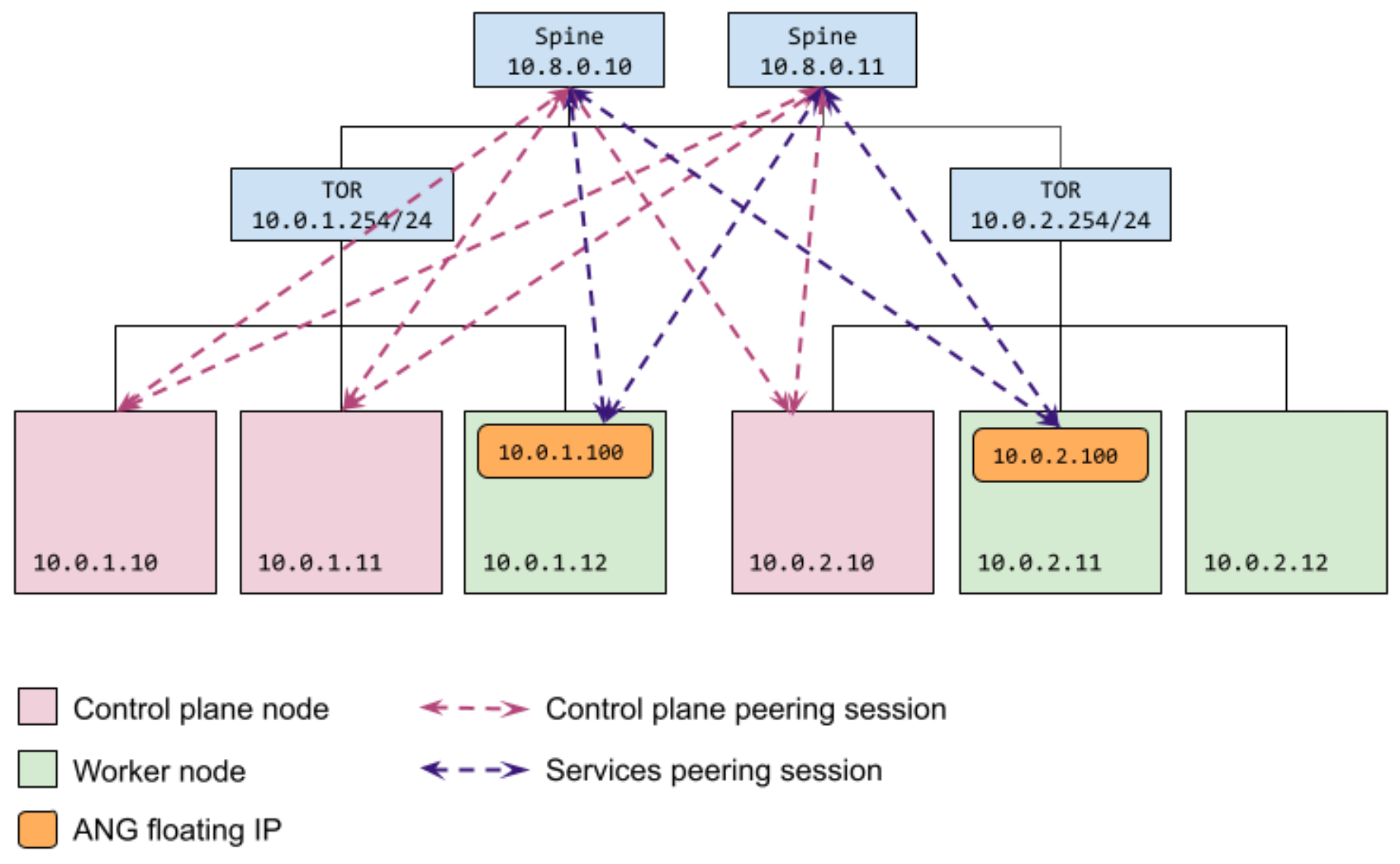
Configure all nodes use the same peers
As shown in the following diagram, this configuration results in a set of
external peers (10.8.0.10 and 10.8.0.11) that are reachable by all nodes.
Control plane nodes (10.0.1.10, 10.0.1.11, and 10.0.2.10) and floating IP
addresses (10.0.1.100 and 10.0.2.100) assigned to data plane nodes all
reach the peers.
The same external peers are both reachable by either of the floating IP
addresses (10.0.1.100 or 10.0.2.100) that are reserved for loadBalancer
Services peering. The floating IP addresses can be assigned to nodes that are in
the same subnet.
As shown in the following cluster configuration sample, you configure the peers
for the control plane nodes, bgpPeers, without specifying controlPlaneNodes.
When no nodes are specified for peers, then all control plane nodes connect to
all peers.
You specify the floating IP addresses to use for Services load-balancing peering
sessions in the AnthosNetworkGateway custom resource. You specify the
corresponding external peers in the BGPLoadBalancer resource.
apiVersion: baremetal.cluster.gke.io/v1
kind: Cluster
metadata:
  name: bm
  namespace: cluster-bm
spec:
...
  loadBalancer:
    mode: bundled

    # type can be 'bgp' or 'layer2'. If no type is specified, we default to layer2.
    type: bgp

    # AS number for the cluster
    localASN: 65001

    bgpPeers:
    - ip: 10.8.0.10
      asn: 65002
    - ip: 10.8.0.11
      asn: 65002

... (other cluster config omitted)
---
apiVersion: networking.gke.io/v1alpha1
kind: AnthosNetworkGateway
metadata:
  name: default
  namespace: cluster-bm
spec:
  floatingIPs:
  - 10.0.1.100
  - 10.0.2.100
---
apiVersion: networking.gke.io/v1alpha1
kind: BGPLoadBalancer
metadata:
  name: bgplb
  namespace: cluster-bm
spec:
  localASN: 65001
  peers:
  - peerIP: 10.8.0.10
    peerASN: 65002
  - peerIP: 10.8.0.11
    peerASN: 65002
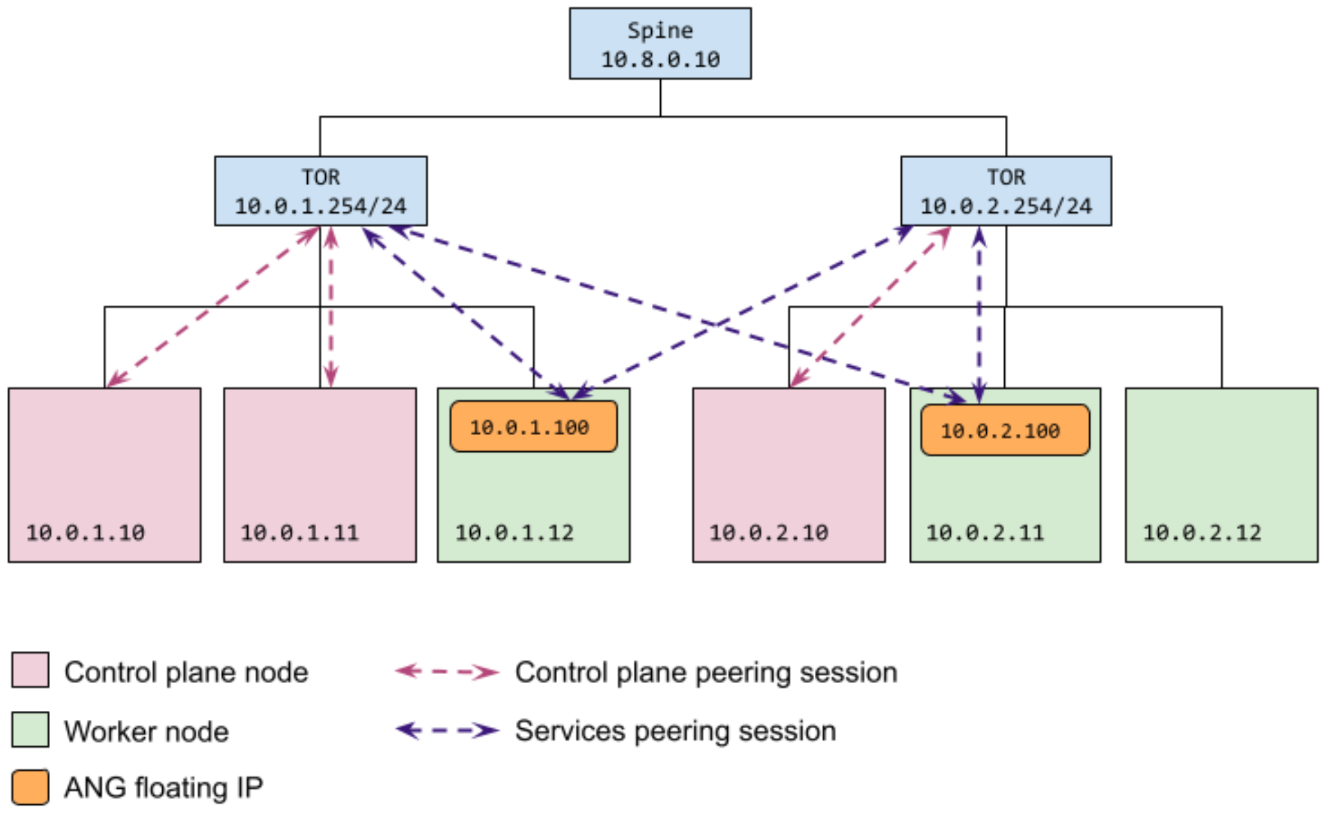
Configure specific control plane nodes to peer with specific external peers
As shown in the following diagram, this configuration results in two control
plane nodes (10.0.1.10 and 10.0.1.11) peering with one external peer
(10.0.1.254). The third control plane node (10.0.2.10) is peering with
another external peer (10.0.2.254). This configuration is useful when you
don't want all nodes to connect to all peers. For example, you may want control
plane nodes to peer with their corresponding top-of-rack (ToR) switches only.
The same external peers are both reachable by either of the floating IP
addresses (10.0.1.100 or 10.0.2.100) that are reserved for Services
load-balancing peering sessions. The floating IP addresses can be assigned to
nodes that are in the same subnet.
As shown in the following cluster configuration sample, you restrict which
control plane nodes can connect to a given peer by specifying their IP addresses
in the controlPlaneNodes field for the peer in the bgpPeers section.
You specify the floating IP addresses to use for Services load-balancing peering
sessions in the AnthosNetworkGateway custom resource. You specify the
corresponding external peers in the BGPLoadBalancer resource.
apiVersion: baremetal.cluster.gke.io/v1
kind: Cluster
metadata:
  name: bm
  namespace: cluster-bm
spec:
...
  loadBalancer:
    mode: bundled

    # type can be 'bgp' or 'layer2'. If no type is specified, we default to layer2.
    type: bgp

    # AS number for the cluster
    localASN: 65001

    bgpPeers:
    - ip: 10.0.1.254
      asn: 65002
      controlPlaneNodes:
        - 10.0.1.10
        - 10.0.1.11
    - ip: 10.0.2.254
      asn: 65002
      controlPlaneNodes:
        - 10.0.2.10

... (other cluster config omitted)
---
apiVersion: networking.gke.io/v1alpha1
kind: AnthosNetworkGateway
  name: default
  namespace: cluster-bm
spec:
  floatingIPs:
  - 10.0.1.100
  - 10.0.2.100
---
apiVersion: networking.gke.io/v1alpha1
kind: BGPLoadBalancer
metadata:
  name: bgplb
  namespace: cluster-bm
spec:
  localASN: 65001
  peers:
  - peerIP: 10.0.1.254
    peerASN: 65002
  - peerIP: 10.0.2.254
    peerASN: 65002
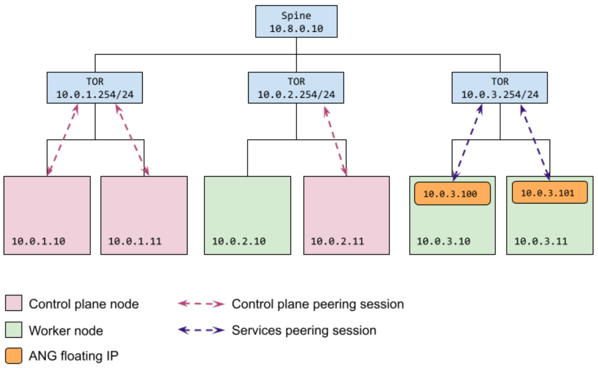
Configure control plane and data plane separately
As shown in the following diagram, this configuration results in two control
plane nodes (10.0.1.10 and 10.0.1.11) peering with one external peer
(10.0.1.254) and the third control plane node (10.0.2.10) peering with
another external peer (10.0.2.254).
A third external peer (10.0.3.254) is reachable by either of the floating IP
addresses (10.0.3.100 or 10.0.3.101) that are reserved for Services
load-balancing peering sessions. The floating IP addresses can be assigned to
nodes that are in the same subnet.
As shown in the following cluster configuration sample, you restrict which
control plane nodes can connect to a given peer by specifying their IP addresses
in the controlPlaneNodes field for the peer in the bgpPeers section.
You specify the floating IP addresses to use for Services load-balancing peering
sessions in the AnthosNetworkGateway custom resource. You specify the
corresponding external peers in the BGPLoadBalancer resource.
apiVersion: baremetal.cluster.gke.io/v1
kind: Cluster
metadata:
  name: bm
  namespace: cluster-bm
spec:
...
  loadBalancer:
    mode: bundled

    # type can be 'bgp' or 'layer2'. If no type is specified, we default to layer2.
    type: bgp

    # AS number for the cluster
    localASN: 65001

    bgpPeers:
    - ip: 10.0.1.254
      asn: 65002
      controlPlaneNodes:
        - 10.0.1.10
        - 10.0.1.11
    - ip: 10.0.2.254
      asn: 65002
      controlPlaneNodes:
        - 10.0.2.11

... (other cluster config omitted)
---
apiVersion: networking.gke.io/v1alpha1
kind: AnthosNetworkGateway
  name: default
  namespace: cluster-bm
spec:
  floatingIPs:
  - 10.0.3.100
  - 10.0.3.101
---
apiVersion: networking.gke.io/v1alpha1
kind: BGPLoadBalancer
  name: bgplb
  namespace: cluster-bm
spec:
  bgp:
    localASN: 65001
    peers:
    - peerIP: 10.0.3.254
      peerASN: 65002
Modify your BGP-based load-balancing configuration
After you have created your cluster configured to use bundled load balancing with BGP, some configuration settings can be updated, but some can't be updated after the cluster is created.
Control plane
Modifications to the control plane load-balancing configuration are not supported during preview.
Services
You can modify the BGP peering configuration after your cluster has
been created by editing the AnthosNetworkGateway CR and the BGPLoadBalancer
CR. Any modifications to the peering information in these CRs are reflected in
the configuration of the load-balancing solution in the target cluster.
Make updates in the source resources in the cluster namespace in the admin cluster only. Any modifications made to the resources in the target (user) cluster are overwritten.
Troubleshoot
The following sections describe how to access troubleshooting information for bundled load balancing with BGP.
Control plane BGP sessions
The control plane BGP-peering configuration is validated with preflight checks during cluster creation. The preflight checks attempt to:
- Establish a BGP connection with each peer.
- Advertise the control plane VIP.
- Verify that the control plane node can be reached, using the VIP.
If your cluster creation fails preflight checks, then review the preflight check
logs for errors. Datestamped preflight check log files are located in the
baremetal/bmctl-workspace/CLUSTER_NAME/log directory.
At runtime, the control plane BGP speakers run as static pods on each control
plane node and write event information to logs. These static pods include
"bgpadvertiser" in their name, so use the following kubectl get pods command
to view the status of the BGP speaker Pods:
kubectl -n kube-system get pods | grep bgpadvertiser
When the Pods are operating properly, the response should look something like the following:
bgpadvertiser-node-01                            1/1     Running   1          167m
bgpadvertiser-node-02                            1/1     Running   1          165m
bgpadvertiser-node-03                            1/1     Running   1          163m
Use the following command to view the logs for the bgpadvertiser-node-01 Pod:
kubectl -n kube-system logs bgpadvertiser-node-01
Services BGP sessions
The BGPSession resource provides information about current BGP sessions. To
get session information, first get the current sessions, then retrieve the
BGPSession resource for one of the sessions.
Use the following kubectl get command to list the current sessions:
kubectl -n kube-system get bgpsessions
The command returns a list of sessions like the following example:
NAME                            AGE
10.0.1.254-node-01              170m
10.0.1.254-node-05              170m
10.0.3.254-node-01              170m
10.0.3.254-node-05              170m
Use the following kubectl describe command to get the BGPSession resource
for the 10.0.1.254-node-01 BGP session:
kubectl -n kube-system describe bgpsession 10.0.1.254-node-01
The BGPSession resource returned should look something like the following
example:
Name:         10.0.1.254-node-01
Namespace:    kube-system
Labels:       <none>
Annotations:  <none>
API Version:  networking.gke.io/v1alpha1
Kind:         BGPSession
Metadata:
 (omitted)
Spec:
  Floating IP:  10.0.1.178
  Local ASN:    65500
  Local IP:     10.0.1.178
  Node Name:    node-01
  Peer ASN:     65000
  Peer IP:      10.0.1.254
Status:
  Advertised Routes:
    10.0.4.1/32
  Last Report Time:  2021-06-14T22:09:36Z
  State:             Established
Use the kubectl get command to get the BGPAdvertisedRoute resources:
kubectl -n kube-system get bgpadvertisedroutes
The response, which should look similar to the following example, shows the routes currently being advertised:
NAME                                  AGE
bgplb-default-load-balancer-example   5d5h
bgplb-gke-system-istio-ingress        6d
Use kubectl describe to view details about which next hops each route is
advertising.
Manual BGP verification
This section contains instructions for manually verifying your BGP configuration. The procedure sets up a long-running BGP connection so that you can further debug the BGP configuration with your network team. Use this procedure to verify your configuration before you create a cluster or use it if BGP-related preflight checks fail.
Preflight checks automate the following BGP verification tasks:
- Set up a BGP connection to a peer.
- Advertise the control plane VIP.
- Verify that traffic sent from all other cluster nodes to the VIP reaches the current load balancer node.
These tasks are run for each BGP peer on each control plane node. Passing these checks is critical when creating a cluster. The preflight checks, however, don't create long-running connections, so debugging a failure is difficult.
The following sections provide instructions to set up a BGP connection and advertise a route from a single cluster machine to one peer. To test multiple machines and multiple peers, repeat the instructions again, using a different machine and peer combination.
Remember that BGP connections are established from the control plane nodes, so be sure to test this procedure from one of your planned control plane nodes.
Obtain the BGP test program binary
Run the steps in this section on your admin workstation. These steps get the
bgpadvertiser program that is used to test BGP connections and copy it to
control plane nodes where you want to test.
Pull the ansible-runner docker image.
Without Registry Mirror
If you don't use a registry mirror, run the following commands to pull the ansible-runner docker image:
gcloud auth login
gcloud auth configure-docker
docker pull gcr.io/anthos-baremetal-release/ansible-runner:1.10.0-gke.13
With Registry Mirror
If you use a registry mirror, run the following commands to pull the ansible-runner docker image:
docker login REGISTRY_HOST
docker pull REGISTRY_HOST/anthos-baremetal-release/ansible-runner:1.10.0-gke.13
Replace REGISTRY_HOST with the name of your registry mirror server.
To extract the
bgpadvertiserbinary.Without Registry Mirror
To extract the
bgpadvertiserbinary, run the following command:docker cp $(docker create gcr.io/anthos-baremetal-release/ansible-runner:1.10.0-gke.13):/bgpadvertiser .With Registry Mirror
To extract the
bgpadvertiserbinary, run the following command:docker cp $(docker create REGISTRY_HOST/anthos-baremetal-release/ansible-runner:1.10.0-gke.13):/bgpadvertiser .To copy the
bgpadvertiserbinary to the control plane node that you want to test with, run the following command:scp bgpadvertiser USERNAME>@CP_NODE_IP:/tmp/Replace the following:
USERNAME: the username that you use to access the control plane node.CP_NODE_IP: the IP address of the control plane node.
Set up a BGP connection
Run the steps in this section on a control plane node.
Create a configuration file on the node at
/tmp/bgpadvertiser.confthat looks like the following:localIP: NODE_IP localASN: CLUSTER_ASN peers: - peerIP: PEER_IP peerASN: PEER_ASNReplace the following:
NODE_IP: IP address of the control plane node that you're on.CLUSTER_ASN: the autonomous system number used by the cluster.PEER_IP: the IP address of one of the external peers you want to test.PEER_ASN: the autonomous system number for the network that contains the external peer device.
Run the
bgpadvertiserdaemon, substituting the control plane VIP in the following command:/tmp/bgpadvertiser --config /tmp/bgpadvertiser.conf --advertise-ip CONTROL_PLANE_VIPReplace
CONTROL_PLANE_VIPwith the IP address that you're going to use for your control plane VIP. This command causes the BGP advertiser to advertise this address to the peer.View the program output.
At this point, the
bgpadvertiserdaemon starts up, attempts to connect to the peer, and advertises the VIP. The program periodically prints messages (see the following sample output) that includeBGP_FSM_ESTABLISHEDwhen the BGP connection is established.{"level":"info","ts":1646788815.5588224,"logger":"BGPSpeaker","msg":"GoBGP gRPC debug endpoint disabled","localIP":"21.0.101.64"} {"level":"info","ts":1646788815.5596201,"logger":"BGPSpeaker","msg":"Started.","localIP":"21.0.101.64"} I0309 01:20:15.559667 1320826 main.go:154] BGP advertiser started. I0309 01:20:15.561434 1320826 main.go:170] Health status HTTP server started at "127.0.0.1:8080". INFO[0000] Add a peer configuration for:21.0.101.80 Topic=Peer {"level":"info","ts":1646788815.5623345,"logger":"BGPSpeaker","msg":"Peer added.","localIP":"21.0.101.64","peer":"21.0.101.80/4273481989"} DEBU[0000] IdleHoldTimer expired Duration=0 Key=21.0.101.80 Topic=Peer I0309 01:20:15.563503 1320826 main.go:187] Peer applied: {4273481989 21.0.101.80} DEBU[0000] state changed Key=21.0.101.80 Topic=Peer new=BGP_FSM_ACTIVE old=BGP_FSM_IDLE reason=idle-hold-timer-expired DEBU[0000] create Destination Nlri=10.0.0.1/32 Topic=Table {"level":"info","ts":1646788815.5670514,"logger":"BGPSpeaker","msg":"Route added.","localIP":"21.0.101.64","route":{"ID":0,"Metric":0,"NextHop":"21.0.101.64","Prefix":"10.0.0.1/32","VRF":""}} I0309 01:20:15.568029 1320826 main.go:199] Route added: {0 0 21.0.101.64 10.0.0.1/32 } I0309 01:20:15.568073 1320826 main.go:201] BGP advertiser serving... DEBU[0005] try to connect Key=21.0.101.80 Topic=Peer DEBU[0005] state changed Key=21.0.101.80 Topic=Peer new=BGP_FSM_OPENSENT old=BGP_FSM_ACTIVE reason=new-connection DEBU[0005] state changed Key=21.0.101.80 Topic=Peer new=BGP_FSM_OPENCONFIRM old=BGP_FSM_OPENSENT reason=open-msg-received INFO[0005] Peer Up Key=21.0.101.80 State=BGP_FSM_OPENCONFIRM Topic=Peer DEBU[0005] state changed Key=21.0.101.80 Topic=Peer new=BGP_FSM_ESTABLISHED old=BGP_FSM_OPENCONFIRM reason=open-msg-negotiated DEBU[0005] sent update Key=21.0.101.80 State=BGP_FSM_ESTABLISHED Topic=Peer attributes="[{Origin: i} 4273481990 {Nexthop: 21.0.101.64}]" nlri="[10.0.0.1/32]" withdrawals="[]" DEBU[0006] received update Key=21.0.101.80 Topic=Peer attributes="[{Origin: i} 4273481989 4273481990 {Nexthop: 21.0.101.64}]" nlri="[10.0.0.1/32]" withdrawals="[]" DEBU[0006] create Destination Nlri=10.0.0.1/32 Topic=Table DEBU[0035] sent Key=21.0.101.80 State=BGP_FSM_ESTABLISHED Topic=Peer data="&{{[] 19 4} 0x166e528}" DEBU[0065] sent Key=21.0.101.80 State=BGP_FSM_ESTABLISHED Topic=Peer data="&{{[] 19 4} 0x166e528}"
If you do not see these messages, then double-check the BGP configuration parameters in the config file and verify with the network administrator. Now you have a BGP connection set up. You can verify with the network administrator that they see the connection established on their side and that they see the route advertised to them.
Traffic test
To test that the network can forward traffic to the VIP, you must add the VIP to
your control plane node that's running bgpadvertiser. Run the following
command in a different terminal so you can leave the bgpadvertiser running:
Add the VIP to your control plane node:
ip addr add CONTROL_PLANE_VIP/32 dev INTF_NAMEReplace the following:
CONTROL_PLANE_VIP: the VIP--advertise-ipargument of thebgpadvertiser.INTF_NAME: the Kubernetes interface on the node. That is, the interface that has the IP address that you put in the Google Distributed Cloud configuration forloadBalancer.bgpPeers.controlPlaneNodes.
Ping the VIP from a different node:
ping CONTROL_PLANE_VIPIf the ping does not succeed, then there may be an issue with the BGP configuration on the network device. Work with your network administrator to verify the configuration and resolve the issue.
Clean up
Be sure to follow these steps to reset the node after you've manually verified that BGP is working. If you don't reset the node properly, the manual setup may interfere with the preflight check or subsequent cluster creation.
Remove the VIP from the control plane node if you added it for the traffic test:
ip addr del CONTROL_PLANE_VIP/32 dev INTF_NAMEOn the control plane node, press
Ctrl+Cin thebgpadvertiserterminal to stop the bgpadvertiser.Verify that no
bgpadvertiserprocesses are running:ps -ef | grep bgpadvertiserIf you see processes running, then stop them using the
killcommand.