| title | description | author | tags | date_published |
|---|---|---|---|---|
How to set up VPN between Cisco ASR and Cloud VPN |
Learn how to build site-to-site IPsec VPN between Cisco ASR and Cloud VPN. |
ashishverm |
Compute Engine, Cloud VPN, Cisco ASR |
2017-08-25 |
Ashish Verma | Technical Program Manager | Google
Contributed by Google employees.
This guide walks you through the process to configure the Cisco ASR 1000 for integration with the Google Cloud VPN Services. This information is provided as an example only. Please note that this guide is not meant to be a comprehensive overview of IPsec and assumes basic familiarity with the IPsec protocol.
The equipment used in the creation of this guide is as follows:
- Vendor: Cisco
- Model: ASR 1009-X
- Software Release: IOS XE 16.6.1
Although this guide is created with ASR 1009-X exactly the same configuration also apply to other ASR 1000 platforms:
- ASR 1001-X
- ASR1002-X
- ASR1001-HX
- ASR1002-HX
- ASR 1006-X
The topology outlined by this guide is a basic site-to-site IPsec VPN tunnel configuration using the referenced device:
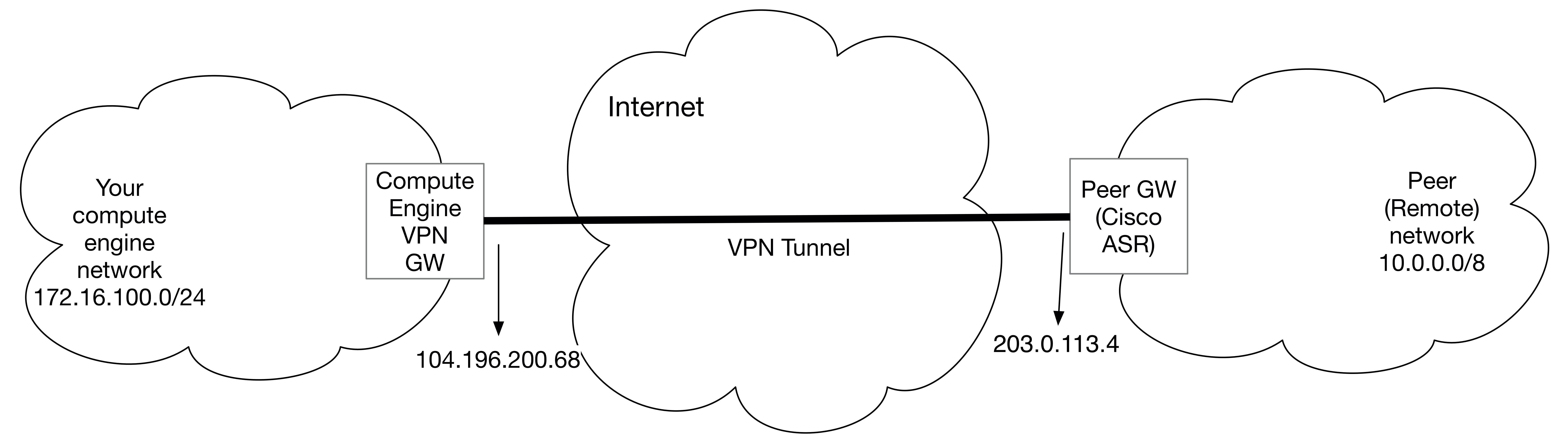
The configuration samples which follow will include numerous value substitutions provided for the purpose of example only. Any references to IP addresses, device IDs, shared secrets or keys account information or project names should be replaced with the appropriate values for your environment when following this guide.
This guide is not meant to be a comprehensive setup overview for the device referenced, but rather is only intended to assist in the creation of IPsec connectivity to Google Cloud VPC networks. The following is a high-level overview of the configuration process which will be covered:
- Configure the base network configurations to establish L3 connectivity
- Set up the Base VPN configuration, including:
- Configure IKEv2 Proposal and Policy
- Configure IKEv2 Keyring
- Configure IKEv2 profile
- Configure IPsec Security Association (SA)
- Configure IPsec transform set
- Configure IPsec profile
- Configure IPsec Static Virtual Tunnel Interface (SVTI)
- Configure Static or Dynamic Routing Protocol to route traffic into the IPsec tunnel
- Testing the IPsec connection
- Advanced VPN configurations
The first step in configuring your Cisco ASR 1000 for use with the Google Cloud VPN service is to ensure that the following prerequisite conditions have been met:
The Cisco ASR 1000 Series Router IPsec application requires:
- Advanced Enterprise Services(SLASR1-AES) or Advanced IP Services Technology Package License (SLASR1-AIS)
- IPsec RTU license (FLASR1-IPsec-RTU)
- Encryption HW module (ASR1002HX-IPsecHW(=) and ASR1001HX-IPsecW(=)) and Tiered Crypto throughput license which applies to ASR1002-HX and ASR1001-HX chassis only.
For a detailed ASR 1000 Series Router license information, refer to the ASR 1000 Routers Ordering Guide.
For the Cisco ASR 1000 IPsec configuration, the following details will be used:
| Parameter | Value |
|---|---|
| IPsec Mode | Tunnel mode |
| Auth protocol | Pre-shared-key |
| Key Exchange | IKEv2 |
| Start | Auto |
| Perfect Forward Secrecy (PFS) | Group 16 |
| Dead Peer Detection (DPD) | 60 5 periodic |
The IPsec configuration used in this guide is specified below:
| Cipher Role | Cipher |
|---|---|
| Encryption | aes-cbc-256 aes-cbc-192 aes-cbc-128 |
| Integrity | sha256 |
| Diffie-Hellman (DH) | group 16 |
| Lifetime | 36,000 seconds (10 hours) |
For dynamic routing you use Cloud Router to establish BGP sessions between the 2 peers.
-
Go to the VPN page in the Google Cloud Platform Console.
-
Click Create VPN connection.
-
Populate the following fields for the gateway:
- Name — The name of the VPN gateway. This name is displayed in the
console and used in by the
gcloudcommand-line tool to reference the gateway. - VPC network — The VPC network containing the instances the VPN gateway
will serve. In this case it is
vpn-scale-test-cisco, a custom VPC network. - Region — The region where you want to locate the VPN gateway.
Normally, this is the region that contains the instances you wish to
reach. Example:
us-east1 - IP address — Select a pre-existing static external IP address.
If you don't have a static external IP address, you can create one by
clicking New static IP address in the pull-down menu. Selected
vpn-scale-test0for this guide.
- Name — The name of the VPN gateway. This name is displayed in the
console and used in by the
-
Populate fields for at least one tunnel:
- Peer IP address —
203.0.113.4Public IP address of the peer gateway. - IKE version — IKEv2 is preferred, but IKEv1 is supported if that is all the peer gateway can manage.
- Shared Secret — Character string used in establishing encryption for that tunnel. You must enter the same shared secret into both VPN gateways. If the VPN gateway device on the peer side of the tunnel doesn't generate one automatically, you can make one up.
- Routing options — Select Dynamic (BGP).
- Cloud router — Select Create cloud router, then populate the following fields. When you are done, click Save and continue.
- Name — The name of the Cloud Router. This name is displayed in the
console and used by the
gcloudcommand-line tool to reference the router. Example:vpn-scale-test-cisco-rtr - Google ASN — The private ASN
(64512 - 65534, 4200000000 - 4294967294) for the router you are
configuring. It can be any private ASN you are not already using.
Example:
65002 - BGP session — Click the pencil icon, then populate the following fields. When you are done, click Save and continue.
- Name —
bgp-peer1 - Peer ASN — The private ASN
(64512 - 65534, 4200000000 - 4294967294) for the router you are
configuring. It can be any private ASN you are not already using.
Example:
65001 - Google BGP IP address — The two BGP interface IP addresses must be
link-local IP addresses belonging to the same /30 subnet in
169.254.0.0/16. Example:169.254.1.1 - Peer BGP IP address — See explanation for Google BGP IP address.
Example:
169.254.1.2
- Peer IP address —
-
Click Create to create the gateway, Cloud Router, and all tunnels, though tunnels will not connect until you've configured the peer router as well.
This step automatically creates the necessary forwarding rules for the gateway and tunnels.
-
Configure your firewall rules to allow inbound traffic from the peer network subnets, and you must configure the peer network firewall to allow inbound traffic from your Compute Engine prefixes.
- Go to the Firewall rules page.
- Click Create firewall rule.
- Populate the following fields:
- Name:
vpnrule1 - VPC network:
my-network - Source filter: IP ranges.
- Source IP ranges: The peer ranges to accept from the peer VPN gateway.
- Allowed protocols and ports: tcp;udp;icmp
- Name:
- Click Create.
-
Create a custom VPC network. You can also use auto VPC network, make sure there is no conflict with your local network range.
gcloud compute networks create vpn-scale-test-cisco --mode custom gcloud compute networks subnets create subnet-1 --network vpn-scale-test-cisco \ --region us-east1 --range 172.16.100.0/24 -
Create a VPN gateway in the desired region. Normally, this is the region that contains the instances you want to reach. This step creates an unconfigured VPN gateway named
vpn-scale-test-cisco-gw-0in your VPC network.gcloud compute target-vpn-gateways create vpn-scale-test-cisco-gw-0 --network \ vpn-scale-test-cisco --region us-east1 -
Reserve a static IP address in the VPC network and region where you created the VPN gateway. Make a note of the created address for use in future steps.
gcloud compute --project vpn-guide addresses create --region us-east1 vpn-static-ip -
Create a forwarding rule that forwards ESP, IKE and NAT-T traffic toward the Cloud VPN gateway. Use the static IP address
vpn-static-ipyou reserved earlier. This step generates a forwarding rule namedfr-esp,fr-udp500,fr-udp4500resp.gcloud compute --project vpn-guide forwarding-rules create fr-esp --region us-east1 \ --ip-protocol ESP --address 35.185.3.177 --target-vpn-gateway vpn-scale-test-cisco-gw-0 gcloud compute --project vpn-guide forwarding-rules create fr-udp500 --region us-east1 \ --ip-protocol UDP --ports 500 --address 35.185.3.177 --target-vpn-gateway vpn-scale-test-cisco-gw-0 gcloud compute --project vpn-guide forwarding-rules create fr-udp4500 --region us-east1 \ --ip-protocol UDP --ports 4500 --address 35.185.3.177 --target-vpn-gateway vpn-scale-test-cisco-gw-0 -
Create Cloud Router as shown below:
gcloud compute --project vpn-guide routers create vpn-scale-test-cisco-rtr --region us-east1 \ --network vpn-scale-test-cisco --asn 65002 -
Create a VPN tunnel on the Cloud VPN Gateway that points toward the external IP address
[CUST_GW_EXT_IP]of your peer VPN gateway. You also need to supply the shared secret. The default, and preferred, IKE version is 2. If you need to set it to 1, use --ike_version 1. The following example sets IKE version to 2. After you run this command, resources are allocated for this VPN tunnel, but it is not yet passing traffic.gcloud compute --project vpn-guide vpn-tunnels create tunnel1 --peer-address 203.0.113.4 \ --region us-east1 --ike-version 2 --shared-secret MySharedSecret --target-vpn-gateway \ vpn-scale-test-cisco-gw-0 --router vpn-scale-test-cisco-rtr -
Update the Cloud Router config to add a virtual interface (--interface-name) for the BGP peer. The BGP interface IP address must be a link-local IP address belonging to the IP address range
169.254.0.0/16and it must belong to same subnet as the interface address of the peer router. The netmask length is recommended to be 30. Make sure each tunnel has a unique pair of IPs. Alternatively, you can leave--ip-addressand--mask-lengthblank, and leave--peer-ip-addressblank in the next step, and IP addresses will be automatically generated for you.gcloud compute --project vpn-guide routers add-interface vpn-scale-test-cisco-rtr \ --interface-name if-1 --ip-address 169.254.1.1 --mask-length 30 --vpn-tunnel tunnel1 --region us-east1 -
Update the Cloud Router config to add the BGP peer to the interface. This example uses ASN 65001 for the peer ASN. You can use your public ASN or private ASN (64512 - 65534, 4200000000 - 4294967294) that you are not already using in the peer network. The BGP peer interface IP address must be a link-local IP address belonging to the IP address range
169.254.0.0/16. It must belong to same subnet as the Google Cloud interface. Make sure each tunnel has a unique pair of IPs.gcloud compute --project vpn-guide routers add-bgp-peer vpn-scale-test-cisco-rtr --peer-name \ bgp-peer1 --interface if-1 --peer-ip-address 169.254.1.2 --peer-asn 65001 --region us-east1 -
View details of the Cloud Router and confirm your settings.
gcloud compute --project vpn-guide routers describe vpn-scale-test-cisco-rtr --region us-east1 -
Create firewall rules to allow traffic between the on-premises network and Google Cloud VPC networks.
gcloud compute --project vpn-guide firewall-rules create vpnrule1 --network vpn-scale-test-cisco \ --allow tcp,udp,icmp --source-ranges 10.0.0.0/8
This section provides the steps to create Cloud VPN on Google Cloud. There are two
ways to create VPN on Google Cloud, using Cloud Console and the gcloud
command-line tool. The upcoming section provide details to both in detail below:
-
Go to the VPN page in the Google Cloud Platform Console.
-
Click Create VPN connection.
-
Populate the following fields for the gateway:
- Name — The name of the VPN gateway. This name is displayed in the
console and used by the
gcloudcommand-line tool to reference the gateway. - VPC network — The VPC network containing the instances the VPN gateway
will serve. In this case it is
vpn-scale-test-cisco, a custom VPC network. Ensure this network does not conflict with your on-premises networks. - Region — The region where you want to locate the VPN gateway.
Normally, this is the region that contains the instances you wish to
reach. Example:
us-east1 - IP address — Select a pre-existing static external IP address.
If you don't have a static external IP address, you can create one by
clicking New static IP address in the pull-down menu. Selected
vpn-scale-test0for this guide.
- Name — The name of the VPN gateway. This name is displayed in the
console and used by the
-
Populate fields for at least one tunnel:
- Peer IP address — Enter your on-premises public IP address here, with the
above mentioned topology it is
203.0.113.4 - IKE version — IKEv2 is preferred, but IKEv1 is supported if that is all the peer gateway can manage.
- Shared secret — Used in establishing encryption for that tunnel. You must enter the same shared secret into both VPN gateways. If the VPN gateway device on the other side of the tunnel doesn't generate one automatically, you can make one up.
- Remote network IP range —
10.0.0.0/8. The range, or ranges, of the peer network, which is the network on the other side of the tunnel from the Cloud VPN gateway you are currently configuring. - Local subnets — Specifies which IP ranges will be routed through the tunnel. This value cannot be changed after the tunnel is created because it is used in the IKE handshake.
- Select the gateway's entire subnet in the pull-down menu. Or, you can leave it blank since the local subnet is the default.
- Leave Local IP ranges blank except for the gateway's subnet.
- Peer IP address — Enter your on-premises public IP address here, with the
above mentioned topology it is
-
Click Create to create the gateway and initiate all tunnels, though tunnels will not connect until you've completed the additional steps below. This step automatically creates a network-wide route and necessary forwarding rules for the tunnel.
-
Configure your firewall rules to allow inbound traffic from the peer network subnets, and you must configure the peer network firewall to allow inbound traffic from your Compute Engine prefixes.
- Go to the Firewall rules page.
- Click Create firewall rule.
- Populate the following fields:
- Name:
vpnrule1 - VPC network:
vpn-scale-test-cisco - Source filter: IP ranges.
- Source IP ranges: The peer ranges to accept from the peer VPN gateway.
- Allowed protocols and ports:
tcp;udp;icmp
- Name:
- Click Create.
-
Create a custom VPC network. You can also use auto VPC network, make sure there is no conflict with your local network range.
gcloud compute networks create vpn-scale-test-cisco --mode custom gcloud compute networks subnets create subnet-1 --network vpn-scale-test-cisco \ --region us-east1 --range 172.16.100.0/24 -
Create a VPN gateway in the desired region. Normally, this is the region that contains the instances you wish to reach. This step creates an unconfigured VPN gateway named
vpn-scale-test-cisco-gw-0in your VPC network.gcloud compute target-vpn-gateways create vpn-scale-test-cisco-gw-0 \ --network vpn-scale-test-cisco --region us-east1 -
Reserve a static IP address in the VPC network and region where you created the VPN gateway. Make a note of the created address for use in future steps.
gcloud compute --project vpn-guide addresses create --region us-east1 vpn-static-ip -
Create a forwarding rule that forwards ESP, IKE and NAT-T traffic toward the Cloud VPN gateway. Use the static IP address
vpn-static-ipyou reserved earlier. This step generates a forwarding rule namedfr-esp,fr-udp500,fr-udp4500resp.gcloud compute --project vpn-guide forwarding-rules create fr-esp --region us-east1 \ --ip-protocol ESP --address 35.185.3.177 --target-vpn-gateway vpn-scale-test-cisco-gw-0 gcloud compute forwarding-rules create fr-udp500 --project vpn-guide --region us-east1 \ --address 104.196.200.68 --target-vpn-gateway vpn-scale-test-cisco-gw-0 --ip-protocol=UDP --ports 500 gcloud compute forwarding-rules create fr-udp4500 --project vpn-guide --region us-east1 \ --address 104.196.200.68 --target-vpn-gateway vpn-scale-test-cisco-gw-0 --ip-protocol=UDP --ports 4500 -
Create a VPN tunnel on the Cloud VPN Gateway that points toward the external IP address
[CUST_GW_EXT_IP]of your peer VPN gateway. You also need to supply the shared secret. The default, and preferred, IKE version is 2. If you need to set it to 1, use --ike_version 1. The following example sets IKE version to 2. After you run this command, resources are allocated for this VPN tunnel, but it is not yet passing traffic.gcloud compute --project vpn-guide vpn-tunnels create tunnel1 --peer-address 203.0.113.4 \ --region us-east1 --ike-version 2 --shared-secret MySharedSecret --target-vpn-gateway \ vpn-scale-test-cisco-gw-0 --local-traffic-selector=172.16.100.0/24 -
Use a static route to forward traffic to the destination range of IP addresses ([CIDR_DEST_RANGE]) in your local on-premises network. You can repeat this command to add multiple ranges to the VPN tunnel. The region must be the same as for the tunnel.
gcloud compute --project vpn-guide routes create route1 --network [NETWORK] --next-hop-vpn-tunnel \ tunnel1 --next-hop-vpn-tunnel-region us-east1 --destination-range 10.0.0.0/8 -
Create firewall rules to allow traffic between on-premises network and Google Cloud VPC networks.
gcloud compute --project vpn-guide firewall-rules create vpnrule1 --network vpn-scale-test-cisco \ --allow tcp,udp,icmp --source-ranges 10.0.0.0/8
This section provides the base network configuration of Cisco ASR 1000 to establish network connectivity. At least one internal facing interface is required to connect to your own network, and one external facing interface is required to connect to Google Cloud. A sample interface configuration is provided below for reference:
! Internal interface configuration
interface TenGigabitEthernet0/0/2
description internal facing interface
ip address 10.0.200.1 255.0.0.0
!
!External interface configuration
interface TenGigabitEthernet0/0/0
description external facing interface
ip address 203.0.113.4 255.255.255.224
Create an Internet Key Exchange (IKE) version 2 proposal object. IKEv2 proposal objects contain the parameters required for creating IKEv2 proposals when defining remote access and site-to-site VPN policies. IKE is used to authenticate IPsec peers, negotiate and distribute IPsec encryption keys, and automatically establish IPsec security associations (SAs). The default proposal associated with the default policy is used for negotiation. An IKEv2 policy with no proposal is considered incomplete. In this block, the following parameters are set:
-
Encryption algorithm - set to
AES-CBC-256,AES-CBC-192,AES-CBC-128 -
Integrity algorithm - set to SHA256
-
Diffie-Hellman group - set to 16
crypto ikev2 proposal VPN_SCALE_TEST_IKEV2_PROPOSAL encryption aes-cbc-256 aes-cbc-192 aes-cbc-128 integrity sha256 group 16 ! crypto ikev2 policy VPN_SCALE_TEST_IKEV2_POLICY proposal VPN_SCALE_TEST_IKEV2_PROPOSAL
The IKEv2 keyring is associated with an IKEv2 profile and hence, caters to a set of peers that match the IKEv2 profile.
crypto ikev2 keyring VPN_SCALE_TEST_KEY
peer GCP1
address 104.196.200.68
pre-shared-key MySharedSecret
!
An IKEv2 profile must be configured and must be attached to an IPsec profile on both the IKEv2 initiator and responder. In this block, the following parameters are set:
-
IKEv2 Lifetime - set the lifetime of the security associations (after which a reconnection will occur). Set to 36,000 seconds as recommended configuration on ASR 1000 router.
-
DPD – set the dead peer detection interval and retry interval, if there are no response from the peer, the SA created for that peer is deleted. Set to 60 seconds keepalive interval and 5 seconds retry interval as recommended configuration on ASR 1000 router.
crypto ikev2 profile VPN_SCALE_TEST_IKEV2_PROFILE match address local interface TenGigabitEthernet0/0/0 match identity remote any authentication local pre-share authentication remote pre-share keyring local VPN_SCALE_TEST_KEY lifetime 36000 dpd 60 5 periodic
Create IPsec security-association (SA) rules. A security association is a relationship between two or more entities that describes how the entities will use security services to communicate securely. During tunnel establishment, the two peers negotiate security associations that govern authentication, encryption, encapsulation, and key management. These negotiations involve two phases: first, to establish the tunnel (the IKE SA) and second, to govern traffic within the tunnel (the IPsec SA). The following commands set the SA lifetime and timing parameters.
-
IPsec SA lifetime– 1 hour is the recommended value on ASR 1000 router. -
IPsec SA replay window-size– 1024 is the recommended value on ASR 1000 router.crypto ipsec security-association lifetime seconds 3600 crypto ipsec security-association replay window-size 1024
A transform set represents a certain combination of security protocols and algorithms. During the IPsec SA negotiation, the peers agree to use a particular transform set for protecting a particular data flow.
crypto ipsec transform-set VPN_SCALE_TEST_TS esp-aes 256 esp-sha-hmac
mode tunnel
Defines the IPsec parameters that are to be used for IPsec encryption between two IPsec routers in IPsec profile configuration. In this block, the following parameters are set
-
Perfect Forward Secrecy (PFS) - PFS ensures that the same key will not be generated again, so forces a new diffie-hellman key exchange. Set to group16 as recommended configuration on ASR 1000 router.
-
SA Lifetime - set the lifetime of the security associations (after which a reconnection will occur). Set to
3600 secondsas recommended configuration on ASR 1000 router.crypto ipsec profile VPN_SCALE_TEST_VTI set security-association lifetime seconds 3600 set transform-set VPN_SCALE_TEST_TS set pfs group16 set ikev2-profile VPN_SCALE_TEST_IKEV2_PROFILE
A tunnel interface is configured to be the logical interface associated with the tunnel. All traffic routed to the tunnel interface will be encrypted and transmitted to Google Cloud. Similarly, traffic from Google Cloud will be logically received on this interface.
Association with the IPsec security association is done through the
tunnel protection command.
Adjust the maximum segment size (MSS) value of TCP packets going through a router. The recommended value is 1360 when the number of IP MTU bytes is set to 1400. With these recommended settings, TCP sessions quickly scale back to 1400-byte IP packets so the packets will "fit" in the tunnel.
!
interface Tunnel1
ip address 169.254.0.58 255.255.255.252
ip mtu 1400
ip tcp adjust-mss 1360
tunnel source TenGigabitEthernet0/0/0
tunnel mode ipsec ipv4
tunnel destination 104.196.200.68
tunnel protection ipsec profile VPN_SCALE_TEST_VTI
!
BGP is used within the tunnel to exchange prefixes between Google Cloud and the ASR 1000 router. Google Cloud will announce the prefix corresponding to your Cloud.
BGP timers are adjusted to provide more rapid detection of outages.
To advertise additional prefixes to Google Cloud, copy the "network" statement and identify the prefix you wish to advertise. Make sure the prefix is present in the routing table of the ASR 1000 with a valid next-hop.
router bgp 65001
bgp log-neighbor-changes
neighbor 169.254.0.1 description BGP session over Tunnel1
neighbor 169.254.0.1 remote-as 65002
neighbor 169.254.0.1 timers 20 60 60
!
address-family ipv4
network 10.0.0.0
neighbor 169.254.0.1 activate
exit-address-family
or
Statically route traffic toward the network in Google Cloud to the Tunnel interface.
ip route 172.16.100.0 255.255.255.0 Tunnel 1
Check Best practices for further recommendations on peer configurations.
To save the running configuration and set it as the default startup, run the following command on Cisco IOS terminal:
copy run start
cisco-asr#ping 172.16.100.2 source 10.0.200.1
Type escape sequence to abort.
Sending 5, 100-byte ICMP Echos to 172.16.100.2, timeout is 2 seconds:
Packet sent with a source address of 10.0.200.1
!!!!!
Success rate is 100 percent (5/5), round-trip min/avg/max = 18/19/20 ms
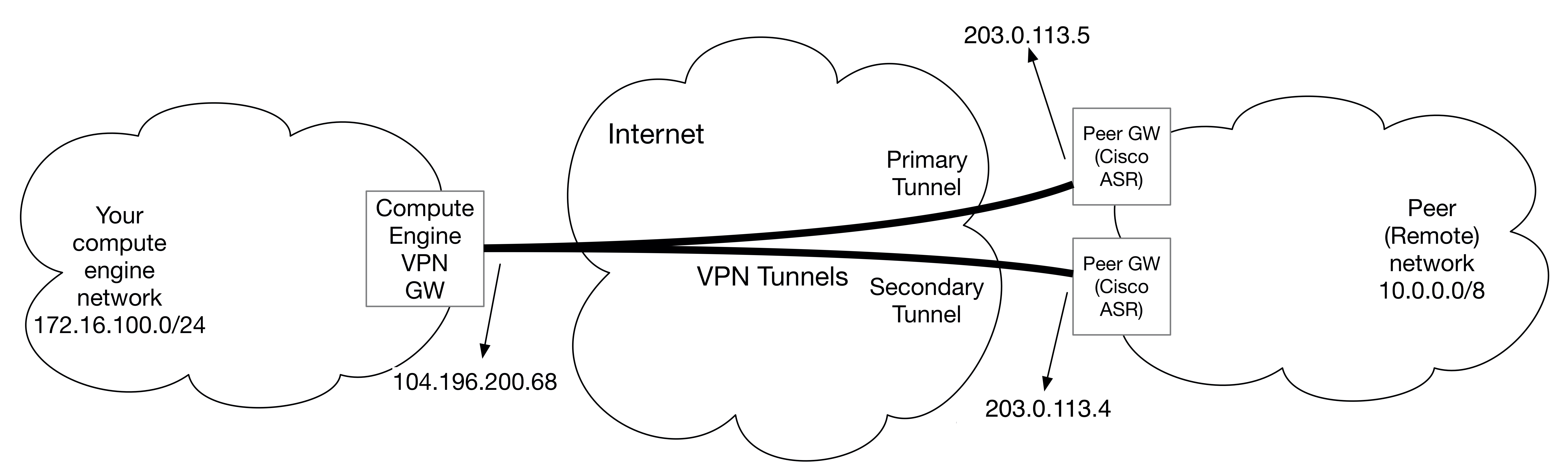
Using redundant tunnels ensures continuous availability in the case of a tunnel fails.
If a Cloud VPN tunnel goes down, it restarts automatically. If an entire virtual device fails, Cloud VPN automatically instantiates a new one with the same configuration, so you don't need to build two Cloud VPN gateways. The new gateway and tunnel connect automatically. For hardware appliances such as Cisco ASR it is recommended that you deploy atleast 2 ASRs and create VPN tunnels to Google Cloud from each for redundancy purposes.
The VPN redundancy configuration example is built based on the IPsec tunnel and BGP configuration illustrated above.
Cisco IOS BGP prefer the path with the highest LOCAL-PREF, the BGP routes are
set with a value of 100 by default, by setting the LOCAL-PREF to 200 for the
routes received from Tunnel1, BGP will choose Tunnel1 as the preferred VPN
tunnel to Google Cloud, in the event of Tunnel 1 failure, BGP will reroute the
traffic to Tunnel2.
crypto ikev2 keyring VPN_SCALE_TEST_KEY
peer GCP1
address 104.196.200.68
pre-shared-key MySharedSecret
peer GCP2
address 35.186.108.199
pre-shared-key MySharedSecret
!
interface Tunnel1
description VPN tunnel to the east coast DC
ip address 169.254.0.2 255.255.255.252
ip mtu 1400
ip tcp adjust-mss 1360
tunnel source TenGigabitEthernet0/0/0
tunnel mode ipsec ipv4
tunnel destination 104.196.200.68
tunnel protection ipsec profile VPN_SCALE_TEST_VTI
!
interface Tunnel2
description VPN tunnel to the west coast DC
ip address 169.254.0.6 255.255.255.252
ip mtu 1400
ip tcp adjust-mss 1360
tunnel source TenGigabitEthernet0/0/0
tunnel mode ipsec ipv4
tunnel destination 35.186.108.199
tunnel protection ipsec profile VPN_SCALE_TEST_VTI_2
!
router bgp 65001
bgp log-neighbor-changes
neighbor 169.254.0.1 description BGP session over Tunnel1
neighbor 169.254.0.1 remote-as 65002
neighbor 169.254.0.1 timers 20 60 60
neighbor 169.254.0.5 description BGP session over Tunnel2
neighbor 169.254.0.5 remote-as 65002
neighbor 169.254.0.5 timers 20 60 60
!
address-family ipv4
network 10.0.0.0
neighbor 169.254.0.1 activate
neighbor 169.254.0.1 route-map LP200 in
neighbor 169.254.0.5 activate
exit-address-family
!
route-map LP200 permit 10
set local-preference 200
To ensure symmetry in your traffic flow, you can configure MED to influence the inbound traffic from Google Cloud for the same tunnel you are sending outbound traffic to. Note that lower the MED, higher the preference.
router bgp 65001
address-family ipv4
neighbor 169.254.0.1 route-map SET-MED-10 out
neighbor 169.254.0.5 activate
exit-address-family
!
route-map SET-MED-10 permit 10
set metric 10
If you are using static routing then instead of BGP configurations mentioned above, you can change the metric (higher the metric lower the preference) for your static route as shown below:
cisco-asr#ip route 172.16.100.0 255.255.255.0 Tunnel2 10
With dynamic routing you have an option to define advertised-route-priority,
lower priority is preferred. More details can be found here.
Note that if you have local_preference configured on the peer network as
mentioned above, BGP will prefer the higher local_preference first.
gcloud compute --project vpn-guide routers add-bgp-peer vpn-scale-test-cisco-rtr --peer-name \
bgp-peer1 --interface if-1 --peer-ip-address 169.254.1.2 --peer-asn 65001 --region us-east1 \
--advertised-route-priority=2000
When using static routing, Google Cloud provides you an option to customize the priority in case there are multiple routes with the same prefix length. In order to have symmetric traffic flow make sure that you set the priority of your secondary tunnel to higher value than the primary tunnel (default priority is 1000). To define the route priority run the below command.
gcloud compute --project vpn-guide routes create route2 --network vpn-scale-test-cisco \
--next-hop-vpn-tunnel tunnel1 --next-hop-vpn-tunnel-region us-east1 --destination-range \
10.0.0.0/8 --priority=2000
cisco-asr#sh ip bgp 172.16.100.0
BGP routing table entry for 172.16.100.0/24, version 690
Paths: (3 available, best #1, table default)
Multipath: eBGP
Flag: 0x404200
Advertised to update-groups:
18
Refresh Epoch 1
65002
169.254.0.1 from 169.254.0.1 (169.254.0.1)
Origin incomplete, metric 100, localpref 2000, valid, external, best
rx pathid: 0, tx pathid: 0x0
Refresh Epoch 1
65002, (received-only)
169.254.0.1 from 169.254.0.1 (169.254.0.1)
Origin incomplete, metric 100, localpref 100, valid, external
rx pathid: 0, tx pathid: 0
Refresh Epoch 1
65002
169.254.0.57 from 169.254.0.57 (169.254.0.1)
Origin incomplete, metric 100, localpref 100, valid, external
rx pathid: 0, tx pathid: 0
cisco-asr#sh ip cef 172.16.100.0
172.16.100.0/24
nexthop 169.254.0.1 Tunnel1
As documented in the advanced configurations, each Cloud VPN tunnel can support up to 3 Gbps when the traffic is traversing a direct peering link, or 1.5 Gbps when traversing the public Internet. To increase the VPN throughput the recommendation is to add multiple Cloud VPN gateway on the same region to load balance the traffic across the tunnels. The 2 VPN tunnels configuration example here is built based on the IPsec tunnel and BGP configuration illustrated above, can be expanded to more tunnels if required.
The ASR 1000 router run cef load balancing based on source and destination ip address hash, each VPN tunnels will be treated as an equal cost path by routing, it can support up to 16 equal cost paths load balancing.
crypto ikev2 keyring VPN_SCALE_TEST_KEY
peer GCP1
address 104.196.200.68
pre-shared-key MySharedSecret
peer GCP3
address 35.185.3.177
pre-shared-key MySharedSecret
!
interface Tunnel1
description VPN tunnel1 to same region GCP for load balancing
ip address 169.254.0.2 255.255.255.252
ip mtu 1400
ip tcp adjust-mss 1360
tunnel source TenGigabitEthernet0/0/0
tunnel mode ipsec ipv4
tunnel destination 104.196.200.68
tunnel protection ipsec profile VPN_SCALE_TEST_VTI
!
interface Tunnel3
description VPN tunnel3 to the same region GCP for load balancing
ip address 169.254.0.10 255.255.255.252
ip mtu 1400
ip tcp adjust-mss 1360
tunnel source TenGigabitEthernet0/0/0
tunnel mode ipsec ipv4
tunnel destination 35.185.3.177
tunnel protection ipsec profile VPN_SCALE_TEST_VTI_3
!
router bgp 65001
bgp log-neighbor-changes
neighbor GCP peer-group
neighbor GCP remote-as 65002
neighbor GCP timers 20 60 60
neighbor 169.254.0.1 peer-group GCP
neighbor 169.254.0.9 peer-group GCP
!
address-family ipv4
network 10.0.0.0
neighbor 169.254.0.1 activate
neighbor 169.254.0.9 activate
maximum-paths 16
exit-address-family
!
Google Cloud does ECMP by default so there is no additional configuration required apart from creating x number of tunnels where x depends on your throughput requirements. You can either use a single VPN gateway to create multiple tunnels or create separate VPN gateway for each tunnel.
Actual performance vary depending on the following factors:
- Network capacity between the two VPN peers.
- The capabilities of the peer device. See your device's documentation for more information.
- Packet size. Because processing happens on a per-packet basis, having a significant percentage of smaller packets can reduce overall throughput.
- High RTT and packet loss rates can greatly reduce throughput for TCP.
The IPsec tunnel can be tested from the router by using ICMP to ping a host on
Google Cloud. Be sure to use the inside interface on the ASR 1000.
cisco-asr#ping 172.16.100.2 source 10.0.200.1
Type escape sequence to abort.
Sending 5, 100-byte ICMP Echos to 172.16.100.2, timeout is 2 seconds:
Packet sent with a source address of 10.0.200.1
!!!!!
Success rate is 100 percent (5/5), round-trip min/avg/max = 18/19/20 ms
Please refer to the troubleshooting ASR1k made easy for
- The ASR 1000 system architecture
- IPsec Packet Flow
- IPsec show command
- Conditional feature debugging
- Packet Tracer
- IOS XE resource monitoring
Please refer to the following documentation for ASR 1000 Platform feature configuration guide and datasheet:
- Security for VPNs with IPsec
- Internet Key Exchange Version 2
- IPsec Virtual Tunnel Interface
- BGP Configuration Guide
- Load Balancing Configuration Guide
- ASR 1000 Routers Datasheet
- ASR 1000 ESP Datasheet
- ASR 1000 Ordering Guide
- IOS-XE NGE Support Product Tech Note
Refer to the following documentation for common error messages and debug commands:
- IPsec Troubleshooting: Understanding and Using debug Commands
- Resolve IP Fragmentation, MTU, MSS, and PMTUD Issues with GRE and IPsec
- Invalid SPI
- IPsec Anti-Replay Check Failures
- IKEv2 Selection Rules for Keyrings and Profiles
- Embedded Packet Capture for IOS-XE
To learn more about Google Cloud networking, refer to below documents: