| title | description | author | tags | date_published |
|---|---|---|---|---|
Cloud VPN interoperability guide for Juniper SRX |
Describes how to build site-to-site IPsec VPNs between Cloud VPN on Google Cloud and Juniper SRX300. |
antiabong,ashishverm |
VPN, interop, Juniper, SRX |
2019-09-12 |
Ashish Verma and Richard Antiabong | Google
Contributed by Google employees.
Juniper, SRX, and Junos are trademarks of Juniper Networks, Inc. or its affiliates in the United States and/or other countries.
Disclaimer: This interoperability guide is intended to be informational in nature and shows examples only. Customers should verify this information by testing it.
Learn how to build site-to-site IPsec VPNs between Cloud VPN on Google Cloud and Juniper SRX300.
For more information about Cloud VPN, see the Cloud VPN overview.
This guide assumes that you have basic knowledge of the IPsec protocol.
Definitions of terms used throughout this guide:
- Google Cloud VPC network: A single virtual network within a single Google Cloud project.
- On-premises gateway: The VPN device on the non-Google Cloud side of the connection, which is usually a device in a physical data center or in another cloud provider's network. Google Cloud instructions are written from the point of view of the Google Cloud VPC network, so on-premises gateway refers to the gateway that's connecting to Google Cloud.
- External IP address or Google Cloud peer address: A single static IP address within a Google Cloud project that exists at the edge of the Google Cloud network.
- Static routing: Manually specifying the route to subnets on the Google Cloud side and to the on-premises side of the VPN gateway.
- Dynamic routing: Google Cloud dynamic routing for VPN using the Border Gateway Protocol (BGP).
Cloud VPN supports the following topologies:
- A site-to-site IPsec VPN tunnel configuration using Cloud Router and providing dynamic routing with the Border Gateway Protocol (BGP).
- A site-to-site IPsec VPN tunnel configuration using static routing.
For detailed topology information, see the following resources:
- For basic VPN topologies, see Cloud VPN overview.
- For redundant topologies, the Cloud VPN documentation on redundant and high-throughput VPNs.
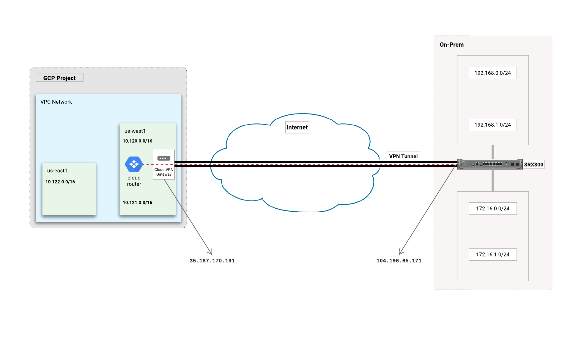
This tutorial uses the topology shown below as a guide to create the SRX300 configurations and Google Cloud environment:
The equipment used in this guide is as follows:
- Vendor: Juniper
- Model: SRX300
- Software release: Junos software release 15.1X49-D100.6
Although the steps in this guide use Juniper SRX300, this guide also applies to the following SRX platforms:
- SRX220 and SRX240
- SRX550
- SRX1400
- SRX3400
- vSRX
Follow the steps in this section to prepare for VPN configuration.
Important: Throughout these procedures, you assign names to entities such as the VPC network, subnet, and IP address. Each time you assign a name, make a note of it, because you often need to use those names in later procedures.
Make sure that you have a Google Cloud account. When you begin, you must select or create a Google Cloud project where you will build the VPN. For details, see Creating and managing projects.
To create a Google Cloud network, a subnetwork, and other entities described in this guide, you must be able to sign in to Google Cloud as a user who has the Network Admin role. For details, see Required permissions.
Before you configure your Juniper SRX300 for use with Cloud VPN, make sure that this license is available:
- Junos Software Base (JSB/JB) license for SRX300 or Junos Software Enhanced (JSE/JE) license
For detailed Juniper SRX series license information, refer to SRX Series Services Gateways.
This section covers how to configure Cloud VPN. The preferred approach is to use dynamic routing with the BGP protocol, but this section also includes instructions for configuring static routing.
There are two ways to create VPN gateways on Google Cloud: using the Cloud Console and using the
gcloud command-line tool. This section describes how to perform the tasks using the Cloud
Console. For the gcloud commands for performing these tasks, see the appendix.
Complete the following procedures before configuring a Google Cloud VPN gateway and tunnel.
These initial tasks are the same whether you are creating an IPsec VPN using dynamic routing or static routing.
-
At the top of the page, select the Google Cloud project you want to use.
Make sure that you use the same Google Cloud project for all of the Google Cloud procedures in this guide.
- In the Cloud Console, go to the VPC networks page.
- Click Create VPC network.
- For Name, enter a name, such as
vpn-juniper-test-network. Remember this name for later. - In the Subnets section, for Subnet creation mode, select Custom.
- In the New subnet section, enter the following values:
- Name: The name for the subnet, such as
vpn-subnet-1. - Region: The region that is geographically closest to the on-premises gateway, such as
us-east1. - IP address range: An IP address range, such as
172.16.100.0/24.
- Name: The name for the subnet, such as
- In the New subnet section, click Done.
- Click Create.
The creation of the network and its subnet can take a minute or more.
-
In the Cloud Console, go to the External IP addresses page.
-
Click Reserve static address.
-
For Name, enter a name, such as
vpn-test-static-ip. Remember the name for later. -
For Region, select the region where you want to locate the VPN gateway. Normally, this is the region that contains the instances you want to reach.
-
Click Reserve.
It can take several seconds for your static external IP address to appear on the External IP addresses page.
-
Make a note of the IP address so that you can use it to configure the VPN gateway later.
For dynamic routing, you use Cloud Router to establish BGP sessions between Google Cloud and the on-premises Juniper SRX300 equipment. We recommend dynamic routing over static routing where possible, as discussed in the Cloud VPN overview and Cloud VPN network and tunnel routing documents.
-
In the Cloud Console, go to the VPN page.
-
Click Create VPN connection.
-
Choose Claasic VPN and click Continue.
-
Set the following values for the VPN gateway:
- Name: The name of the VPN gateway. This name is displayed in the Cloud Console and is used by the
gcloudcommand-line tool to refer to the gateway. Use a name likevpn-test-juniper-gw-1. - Network: The VPC network that you created previously (for example,
vpn-juniper-test-network) that contains the instances that the VPN gateway will serve. - Region: Normally, you put the gateway in the region that contains the instances that you want to reach.
- IP address: Select the static external IP address (for example,
vpn-test-static-ip) that you created for this gateway in the previous section.
- Name: The name of the VPN gateway. This name is displayed in the Cloud Console and is used by the
-
Set the following values for at least one tunnel:
- Name: The name of the VPN tunnel, such as
vpn-test-tunnel1. - Remote peer IP address: The public external IP address of the on-premises VPN gateway.
- IKE version:
IKEv2orIKEv1. IKEv2 is preferred, but you can use IKEv1 if it is the only IKE version that the on-premises gateway can use. - IKE pre-shared key: A character string, also known as a shared secret, that is used in establishing encryption for the tunnel. You must enter the same shared secret into both VPN gateways. For more information, see Generating a strong pre-shared key.
- Name: The name of the VPN tunnel, such as
-
Under Routing options, select the Dynamic (BGP) tab.
-
In the Cloud router menu, select Create cloud router and set the following values in the Create a cloud router dialog:
- Name: The name of the Cloud Router, such as
vpn-test-juniper-rtr. This name is displayed in the Cloud Console. If you use thegcloudcommand-line tool to perform VPN tasks, you use this name to refer to the router. - Google ASN: The private ASN for the router you are configuring. It can be
any private ASN in the range
64512–65534or4200000000–4294967294that you are not already using. Example:65002.
- Name: The name of the Cloud Router, such as
-
Click Save and continue.
-
Next to the BGP session menu, click the Add BGP session button (pencil icon) and set the following values:
- Name: A name for the session, such as
bgp-peer1. - Peer ASN: The private ASN for the on-premises VPN device you are
configuring. It can be any private ASN in the range
64512–65534or4200000000–4294967294that you are not already using. Example:65001. - Google BGP IP address: A link-local IP address that belongs to
the same
/30subnet in169.254.0.0/16. Example:169.254.1.1. - Peer BGP IP address: A link-local IP address for the on-premises peer. Example:
169.254.1.2. For details, see this explanation of dynamic routing for VPN tunnels in VPC networks. - Remote network IP range: The IP address range of the on-premises subnet on the other side of the tunnel from this gateway.
- Advertised route priority: Configure this option if you want to set up redundant or high-throughput VPNs as described in advanced VPN configurations. Note that if you don't need advanced VPN now, you will need to configure a new VPN tunnel later to support it. The advertised route priority is the base priority that Cloud Router uses when advertising the "to Google Cloud" routes. For more information, see Route metrics. Your on-premises VPN gateway imports these as MED values.
- Name: A name for the session, such as
-
Click Save and continue.
-
Click Create.
The Google Cloud VPN gateway and Cloud Router are initiated, and the tunnel is initiated.
This procedure automatically creates a static route to the on-premises subnet as well as forwarding rules for UDP ports 500 and 4500 and for ESP traffic. The VPN gateways will not connect until you've configured the on-premises gateway and created firewall rules in Google Cloud to allow traffic through the tunnel between the Cloud VPN gateway and the on-premises gateway.
You configure Google Cloud firewall rules to allow inbound traffic from the on-premises network subnets. You configure the on-premises network firewall to allow inbound traffic from your VPC subnet prefixes.
- In the Cloud Console, go to the Firewall rules page.
- Click Create firewall rule.
- Set the following values:
- Name: A name for the firewall rule, such as
vpnrule1. - VPC network: The name of the VPC network that you created previously (for example,
vpn-juniper-test-network). - Source filter: A filter to apply your rule to specific sources of traffic. In this case, choose IP ranges.
- Source IP ranges: The on-premises IP ranges to accept from the on-premises VPN gateway.
- Allowed protocols and ports: The string
tcp;udp;icmp.
- Name: A name for the firewall rule, such as
- Click Create.
This section covers the steps for creating a Google Cloud IPsec VPN using static routing. Both route-based Cloud VPN and policy-based Cloud VPN use static routing. For information on how this works, see the Cloud VPN overview.
Most steps in the procedure for configuring an IPsec VPN using static routing are the same as for configuring an IPsec VPN using dynamic routing. Rather than repeat those steps in the following procedure, the procedure links to the previous section.
- Follow the steps for configuring an IPsec VPN using dynamic routing,
with these changes:
- In the configuration for a tunnel, under Routing options, select Route-based.
- For Remote network IP ranges, set the IP address range or ranges of the on-premises network, which is the network on the other side of the tunnel from the Cloud VPN gateway that you are currently configuring.
- Follow the steps for configuring firewall rules in the previous section, and set the following values:
- Name: A name for the firewall rule, such as
vpnrule1. - VPC network: The name you used earlier for the VPC network, such as
vpn-juniper-test-network. - Source filter: A filter to apply your rule to specific sources of traffic. In this case, choose IP ranges.
- Source IP ranges: The peer ranges to accept from the peer VPN gateway.
- Allowed protocols and ports: The string
tcp;udp;icmp.
- Name: A name for the firewall rule, such as
Follow the procedure listed in the configuration code snippet below to create the base Layer 3 network configuration for Juniper SRX300.
At least one internal-facing network interface is required in order to connect to your on-premises network, and one external-facing interface is required in order to connect to Google Cloud.
A sample interface configuration is provided below for reference:
[edit]
root@vsrx#
# Internal interface configuration
set interfaces ge-0/0/1 unit 0 family inet address 192.168.0.1/24
set interfaces ge-0/0/1 unit 0 description "internal facing interface 1"
set interfaces ge-0/0/2 unit 0 family inet address 192.168.1.1/24
set interfaces ge-0/0/2 unit 0 description "internal facing interface 2"
# External interface configuration
set interfaces ge-0/0/0 unit 0 family inet address 104.196.65.171/31
set interfaces ge-0/0/0 unit 0 description "external facing interface"
# Tunnel interface configuration
set interfaces st0 unit 0 family inet mtu 1460
set interfaces st0 unit 0 family inet address 169.254.0.2/30
Follow the procedures in this section to create the base VPN configuration.
Configuring the vendor side of the VPN network requires you to use IPsec and IKE settings that are compatible with the Google Cloud side of the network. The following table lists settings and information about values compatible with Google Cloud VPN. Use these settings for the procedures in the subsections that follow.
The Juniper SRX300 solution might have its own specifications for replay window size.
| Setting | Description or value |
|---|---|
| IPsec Mode | ESP+Auth Tunnel mode (Site-to-Site) |
| Auth Protocol | psk |
| Shared Secret | Also known as an IKE pre-shared key. Choose a strong password by following these guidelines. The shared secret is very sensitive because it allows access to your network. |
| Start | auto (On-premises device should automatically restart the connection if it drops.) |
| PFS (Perfect Forward Secrecy) | on |
| DPD (Dead Peer Detection) | Recommended: Aggressive. DPD detects when the Cloud VPN restarts and routes traffic using alternate tunnels. |
| INITIAL_CONTACT (sometimes called uniqueids) | Recommended: on (sometimes called restart). The purpose is to detect restarts faster so that perceived downtime is reduced. |
| TSi (Traffic Selector - Initiator) | Subnet networks: the ranges specified by the Google Cloud local traffic selector. If no local traffic selector range was specified because the VPN is in an auto-mode VPC network and is announcing only the gateway's subnet, that subnet range is used. Legacy networks: the range of the network. |
| TSr (Traffic Selector - Responder) | IKEv2: The destination ranges of all of the routes that have the next hop VPN tunnel set to this tunnel on the Google Cloud side. IKEv1: Arbitrarily, the destination range of one of the routes that has the next hop VPN tunnel set to this tunnel on the Google Cloud side. |
| MTU | The MTU of the on-premises VPN device must be set to 1460 or lower. ESP packets leaving the device must not exceed 1460 bytes. You must enable prefragmentation on your device, which means that packets must be fragmented first, then encapsulated. For more information, see MTU considerations. |
| IKE ciphers | For details about IKE ciphers for IKEv1 or IKEv2 supported by Google Cloud, including the additional ciphers for PFS, see Supported IKE ciphers. |
Create an Internet Key Exchange (IKE) version 2 proposal object. IKEv2 proposal objects contain the parameters required for creating IKEv2 proposals when defining remote access and site-to-site VPN policies. IKE is used to authenticate IPsec peers, negotiate and distribute IPsec encryption keys, and automatically establish IPsec security associations (SAs). The default proposal associated with the default policy is used for negotiation. An IKEv2 policy with no proposal is considered incomplete.
In this block, the following parameters are set:
-
Encryption algorithm:
AES-CBC-256 -
Integrity algorithm:
SHA256 -
Diffie-Hellman group:
14 -
IKEv2 Lifetime : The lifetime of the security associations, after which a reconnection will occur. The default on most SRX platforms is 28800 seconds.
[edit]
  root@vsrx#
  set security ike proposal ike-phase1-proposal authentication-method pre-shared-keys
  set security ike proposal ike-phase1-proposal dh-group group14
  set security ike proposal ike-phase1-proposal authentication-algorithm sha-256
  set security ike proposal ike-phase1-proposal encryption-algorithm aes-256-cbc
  set security ike proposal ike-phase1-proposal lifetime-seconds 28800
  set security ike policy ike_pol_onprem-2-gcp-vpn mode main
  set security ike policy ike_pol_onprem-2-gcp-vpn proposals ike-phase1-proposal
  set security ike policy ike_pol_onprem-2-gcp-vpn pre-shared-key ascii-text [*****]
An IKEv2 profile must be configured and must be attached to an IPsec profile on both the IKEv2 initiator and the responder.
In this block, the following parameters are set:
-
DPD: The dead peer detection interval and retry threshold. If there are no responses from the peer, the security association created for that peer is deleted. Set the DPD type to
probe-idle-tunnel, the DPD interval to20, and the DPD retry threshold to4. -
IKE: Set the IKE remote address, IKE external interface, and the IKE version (v2). Set the IKE local identity to the IP address of the external interface. If the SRX device is behind a NAT, the local identity should be configured as the public IP address of the NAT. Where the NAT maps to a pool of public IP addresses, a dedicated 1-to-1 NAT should be configured to the SRX device.
[edit]
  root@vsrx#
  set security ike gateway gw_onprem-2-gcp-vpn ike-policy ike_pol_onprem-2-gcp-vpn
  set security ike gateway gw_onprem-2-gcp-vpn address 35.187.170.191
  set security ike gateway gw_onprem-2-gcp-vpn dead-peer-detection probe-idle-tunnel
  set security ike gateway gw_onprem-2-gcp-vpn dead-peer-detection interval 20
  set security ike gateway gw_onprem-2-gcp-vpn dead-peer-detection threshold 4
  set security ike gateway gw_onprem-2-gcp-vpn external-interface ge-0/0/1.0
  set security ike gateway gw_onprem-2-gcp-vpn version v2-only

#Configure local-identity as public IP address of the VPN device, if behind NAT
  set security ike gateway gw_onprem-2-gcp-vpn local-identity inet 104.196.65.171
Define the IPsec parameters that are used for IPsec encryption between two IPsec routers in IPsec profile configuration.
In this block, the following parameters are set:
-
IPsec SA lifetime: Setting
lifetime-secondsto3600(1 hour) is recommended for most VPN sessions. The default on a Juniper SRX is 3600 seconds. -
Perfect Forward Secrecy (PFS): PFS forces a new Diffie-Hellman key exchange. The same key will not be generated again. This value is set to
group14.[edit] root@vsrx# set security ipsec proposal ipsec-phase2-proposal protocol esp set security ipsec proposal ipsec-phase2-proposal lifetime-seconds 3600 set security ipsec proposal ipsec-phase2-proposal authentication-algorithm hmac-sha-256-128 set security ipsec proposal ipsec-phase2-proposal encryption-algorithm aes-256-cbc set security ipsec policy ipsec_pol_home-2-gcp-vpn perfect-forward-secrecy keys group14 set security ipsec policy ipsec_pol_home-2-gcp-vpn proposals ipsec-phase2-proposal
A tunnel interface is configured to be the logical interface associated with the tunnel. All traffic routed to the tunnel interface will be encrypted and transmitted to Google Cloud. Similarly, traffic from Google Cloud will be logically received on this interface.
Adjust the maximum segment size (MSS) value of TCP packets going through a router. The recommended value is 1360 when the
number of IP MTU bytes is set to 1460.
With these recommended settings, TCP sessions quickly scale back to 1400-byte IP packets so the packets will "fit" in the tunnel.
   [edit]
   root@vsrx#
   set security ipsec vpn home-2-gcp-vpn bind-interface st0.0
   set security ipsec vpn home-2-gcp-vpn ike gateway gw_home-2-gcp-vpn
   set security ipsec vpn home-2-gcp-vpn ike ipsec-policy ipsec_pol_home-2-gcp-vpn
   set security ipsec vpn home-2-gcp-vpn establish-tunnels immediately
   set security flow tcp-mss ipsec-vpn mss 1360
   set security flow tcp-session rst-invalidate-session
Juniper SRX uses security zones to isolate network segments and regulates traffic inbound and outbound from these zones
using security policies. Security zones logically bind interfaces (which may represent network segments). For this
configuration, there are three security zones: the untrust zone, with which the internet-facing interface ge-0/0/0.0 is
bound; the trust zone, with which the internal-facing interfaces ge-0/0/1.0and ge-0/0/2.0 are bound; and the vpn-gcp
zone, with which the VPN tunnel interface st0.0 is bound. In addition to binding interfaces to the defined zones, traffic
destined for the Juniper device is allowed or denied in the security zone configuration; also, address-book configuration
(which can be used in security policies to specify what IP addresses are allowed to pass traffic from a zone) is configured
here. For more information on how to configure security zones, see
Juniper security zone configuration.
Below is the security zone configuration for the on-premises Juniper SRX300 device:
[edit]
root@vsrx#
set security zones security-zone untrust interfaces ge-0/0/0.0 host-inbound-traffic system-services ike
set security zones security-zone vpn-gcp host-inbound-traffic protocols bgp
set security zones security-zone vpn-gcp interfaces st0.0

# Allow BGP Session
set security zones security-zone vpn-gcp host-inbound-traffic protocols bgp

#Address book configuration on-prem prefix
set security zones security-zone trust address-book address 192.168.0.0/24 192.168.0.0/24
set security zones security-zone trust address-book address 192.168.1.0/24 192.168.1.0/24
set security zones security-zone trust address-book address 172.16.0.0/24 172.16.0.0/24
set security zones security-zone trust address-book address 172.16.1.0/24 172.16.1.0/24
set security zones security-zone trust address-book address-set onprem-addr-prefixes address 192.168.0.0/24
set security zones security-zone trust address-book address-set onprem-addr-prefixes address 192.168.1.0/24
set security zones security-zone trust address-book address-set onprem-addr-prefixes address 172.16.0.0/24
set security zones security-zone trust address-book address-set onprem-addr-prefixes address 172.16.1.0/24
set security zones security-zone trust tcp-rst
set security zones security-zone trust host-inbound-traffic system-services all
set security zones security-zone trust host-inbound-traffic protocols all
set security zones security-zone trust interfaces ge-0/0/1.0
set security zones security-zone trust interfaces ge-0/0/2.0
set security zones security-zone untrust screen untrust-screen
set security zones security-zone untrust interfaces ge-0/0/0.0 host-inbound-traffic system-services dhcp
set security zones security-zone untrust interfaces ge-0/0/0.0 host-inbound-traffic system-services tftp
set security zones security-zone untrust interfaces ge-0/0/0.0 host-inbound-traffic system-services ssh
set security zones security-zone untrust interfaces ge-0/0/0.0 host-inbound-traffic system-services ike
set security zones security-zone vpn-gcp host-inbound-traffic protocols bgp
set security zones security-zone vpn-gcp interfaces st0.0

#Address book configuration for Google Cloud prefixes
set security zones security-zone vpn-gcp address-book address 10.120.0.0/16 10.120.0.0/16
set security zones security-zone vpn-gcp address-book address 10.121.0.0/16 10.121.0.0/16
set security zones security-zone vpn-gcp address-book address-set gcp-addr-prefixes address 10.120.0.0/16
set security zones security-zone vpn-gcp address-book address-set gcp-addr-prefixes address 10.121.0.0/16
Security policies are statements that allow for control to placed on traffic going from a specific source to a specific destination using a specific service or IP address. For more information on security zones, see Juniper security policy configuration.
For the configuration below, the sources and destinations are the zones untrust, trust, and vpn-gcp configured above.
[edit]
root@vsrx#
set security policies from-zone trust to-zone trust policy default-permit match source-address any
set security policies from-zone trust to-zone trust policy default-permit match destination-address any
set security policies from-zone trust to-zone trust policy default-permit match application any
set security policies from-zone trust to-zone trust policy default-permit then permit
set security policies from-zone trust to-zone trust policy trust-to-trust match source-address any
set security policies from-zone trust to-zone trust policy trust-to-trust match destination-address any
set security policies from-zone trust to-zone trust policy trust-to-trust match application any
set security policies from-zone trust to-zone trust policy trust-to-trust then permit
set security policies from-zone trust to-zone untrust policy default-permit match source-address any
set security policies from-zone trust to-zone untrust policy default-permit match destination-address any
set security policies from-zone trust to-zone untrust policy default-permit match application any
set security policies from-zone trust to-zone untrust policy default-permit then permit
set security policies from-zone trust to-zone untrust policy trust-to-untrust match source-address any
set security policies from-zone trust to-zone untrust policy trust-to-untrust match destination-address any
set security policies from-zone trust to-zone untrust policy trust-to-untrust match application any
set security policies from-zone trust to-zone untrust policy trust-to-untrust then permit
set security policies from-zone trust to-zone vpn-gcp policy policy_out_onprem-2-gcp-vpn match source-address onprem-addr-prefixes
set security policies from-zone trust to-zone vpn-gcp policy policy_out_onprem-2-gcp-vpn match destination-address gcp-addr-prefixes
set security policies from-zone trust to-zone vpn-gcp policy policy_out_onprem-2-gcp-vpn match application any
set security policies from-zone trust to-zone vpn-gcp policy policy_out_onprem-2-gcp-vpn then permit
set security policies from-zone vpn-gcp to-zone trust policy policy_in_onprem-2-gcp-vpn match source-address gcp-addr-prefixes
set security policies from-zone vpn-gcp to-zone trust policy policy_in_onprem-2-gcp-vpn match destination-address onprem-addr-prefixes
set security policies from-zone vpn-gcp to-zone trust policy policy_in_onprem-2-gcp-vpn match application any
set security policies from-zone vpn-gcp to-zone trust policy policy_in_onprem-2-gcp-vpn then permit
BGP is used within the tunnel to exchange prefixes between the Google Cloud Router and the Juniper SRX appliance. The Google Cloud Router will announce the prefix corresponding to your Google Cloud VPC.
BGP timers are adjusted to provide more rapid detection of outages.
-
Configure BGP peering between SRX and Cloud Router
[edit] root@vsrx# set protocols bgp group ebgp-peers type external set protocols bgp group ebgp-peers multihop set protocols bgp group ebgp-peers local-as 65501 set protocols bgp group ebgp-peers neighbor 169.254.1.1 peer-as 65500 -
Configure routing policies to inject routes into BGP and advertise it to the Cloud Router. In this case, only
192.168.0.0/24and192.168.1.0/24are advertised:[edit] root@vsrx# set policy-options policy-statement gcp-bgp-policy term 1 from protocol direct set policy-options policy-statement gcp-bgp-policy term 1 from route-filter 192.168.1.0/24 exact set policy-options policy-statement gcp-bgp-policy term 1 then accept set policy-options policy-statement gcp-bgp-policy term 2 from protocol direct set policy-options policy-statement gcp-bgp-policy term 2 from route-filter 192.168.0.0/24 exact set policy-options policy-statement gcp-bgp-policy term 2 then accept set protocols bgp group ebgp-peers export gcp-bgp-policy
Follow the procedure in this section to configure static routing of traffic to the Google Cloud network through the VPN tunnel
interface st0.0.
[edit]
root@vsrx#
set routing-options static route 10.120.0.0/16 next-hop st0.0
set routing-options static route 10.121.0.0/16 next-hop st0.0
For more recommendations about on-premises routing configurations, see Google Cloud best practices.
Use this command to save the on-premises configuration:
root@vsrx# commit and-quit
It's important to test the VPN connection from both sides of a VPN tunnel. For either side, make sure that the subnet that a machine or virtual machine is located in is being forwarded through the VPN tunnel.
First, create VMs/hosts on both sides of the tunnel, depending on the scenario being tested. Make sure that you configure the VMs/hosts on a subnet that will pass traffic through the VPN tunnel.
Instructions for creating virtual machines in Compute Engine are located in the getting started guide.
After VMs have been deployed on both the Google Cloud and the other side of the tunnel (for example, on-premises or another cloud),
you can use an ICMP echo (ping) test to test network connectivity through the VPN tunnel, and you can use telnet or
netcat to test TCP connectivity.
On the Google Cloud side, use the following instructions to test the connection to a machine that's behind the on-premises gateway:
-
In the Cloud Console, go to the VM instances page.
-
Find the Google Cloud virtual machine you created.
-
In the Connect column, click SSH. A browser window opens at the VM command line.
-
Ping a machine that's behind the on-premises gateway:
root@freebsd:~ # ping 192.168.1.91
PING 192.168.1.91 (192.168.1.91): 56 data bytes
64 bytes from 192.168.1.91: icmp_seq=0 ttl=63 time=21.387 ms
64 bytes from 192.168.1.91: icmp_seq=1 ttl=63 time=19.402 ms
64 bytes from 192.168.1.91: icmp_seq=2 ttl=63 time=20.535 ms
64 bytes from 192.168.1.91: icmp_seq=3 ttl=63 time=35.592 ms
64 bytes from 192.168.1.91: icmp_seq=4 ttl=63 time=23.347 ms
64 bytes from 192.168.1.91: icmp_seq=5 ttl=63 time=17.600 ms
64 bytes from 192.168.1.91: icmp_seq=6 ttl=63 time=19.083 ms
64 bytes from 192.168.1.91: icmp_seq=7 ttl=63 time=19.383 ms
64 bytes from 192.168.1.91: icmp_seq=8 ttl=63 time=21.689 ms
64 bytes from 192.168.1.91: icmp_seq=9 ttl=63 time=28.000 ms
^C
--- 192.168.1.91 ping statistics ---
11 packets transmitted, 10 packets received, 9.1% packet loss
round-trip min/avg/max/stddev = 17.600/22.602/35.592/5.129 ms
root@freebsd:~ #
-
Show IKE security associations:
root@vsrx# run show security ike security-associations Index State Initiator cookie Responder cookie Mode Remote Address 7877087 UP 412c5a43aad7682b b6d24ef8bf25e9ea IKEv2 35.187.170.191 -
Show IPsec security associations:
root@vsrx# run show security ipsec security-associations Total active tunnels: 1 ID Algorithm SPI Life:sec/kb Mon lsys Port Gateway <131073 ESP:aes-cbc-256/sha256 9beb1bf0 729/ unlim - root 4500 35.187.170.191 >131073 ESP:aes-cbc-256/sha256 97791a28 729/ unlim - root 4500 35.187.170.191 -
List BGP learned routes:
root@vsrx# run show route protocol bgp inet.0: 11 destinations, 11 routes (11 active, 0 holddown, 0 hidden) + = Active Route, - = Last Active, * = Both 10.120.0.0/16 *[BGP/170] 23:02:00, MED 100, localpref 100 AS path: 65500 ?, validation-state: unverified > to 169.254.0.1 via st0.0 10.121.0.0/16 *[BGP/170] 23:02:00, MED 100, localpref 100 AS path: 65500 ?, validation-state: unverified > to 169.254.0.1 via st0.0 10.122.0.0/16 *[BGP/170] 23:02:00, MED 100, localpref 100 AS path: 65500 ?, validation-state: unverified > to 169.254.0.1 via st0.0 -
Ping an IP address in Google Cloud through the tunnel:
root@vsrx> ping 10.120.0.2 count 5 source 192.168.1.1
PING 10.120.0.2 (10.120.0.2): 56 data bytes
64 bytes from 10.120.0.2: icmp_seq=0 ttl=64 time=20.758 ms
64 bytes from 10.120.0.2: icmp_seq=1 ttl=64 time=20.024 ms
64 bytes from 10.120.0.2: icmp_seq=2 ttl=64 time=23.783 ms
64 bytes from 10.120.0.2: icmp_seq=3 ttl=64 time=19.472 ms
64 bytes from 10.120.0.2: icmp_seq=4 ttl=64 time=21.183 ms

--- 172.16.0.2 ping statistics ---
5 packets transmitted, 5 packets received, 0% packet loss
round-trip min/avg/max/stddev = 19.472/21.044/23.783/1.491 ms

root@vsrx>
This section covers how to configure redundant on-premises VPN gateways and how to get higher throughput through VPN tunnels.
Using redundant on-premises VPN gateways ensures continuous availability when a tunnel fails. The article Redundancy and high-throughput VPNs in the Cloud VPN documentation provides configuration guidelines for both Google Cloud and on-premises VPN gateways, including guidance on setting route priorities for redundant gateways. Juniper SRX devices use chassis clustering to provide high availability. This feature is not supported in the SRX300 series devices. See Chassis Clustering and Chassis Cluster Overview for more information.
To achieve high availability in the SRX300 platform, multiple (at least two) SRX300 devices are needed. The high availability is accomplished by manipulating BGP routing within the devices. This is beyond the scope of this document. See the Juniper BGP Feature Guide for more in-depth information on how to configure BGP (internal and external) and manipulate BGP attributes for different route preferences.
This section contains procedures for configuring route priority settings on Juniper SRX300 and Google Cloud. The Google Cloud instructions assume that you have built each Google Cloud gateway in a set of redundant gateways as described in the dynamic routing section and configured the Advertised route priority field when you configured the VPN gateway. If you didn't do this, then you will need to create a new tunnel and BGP session for the gateways involved and configure the Advertised route priority field as described in the following sections.
Some of the procedures in this section use gcloud commands. For information about using gcloud commands, and about
setting environment variables for parameter values such as the Google Cloud network name, see the
appendix.
Google Cloud Router uses only BGP MED (Multi-Exit Discriminator) values to determine route priorities. For more information, see this page. MED is a routing metric; routes with lower values are considered better routes. MED values on SRX300 devices can be set for all prefixes per neighbor or for specific routes using route filters. See the Configuring BGP MED and Configuring the MED Using Route Filters sections of the Juniper documentation for details of how to set BGP MED in the Juniper SRX300.
This sample configuration sets MED values of all routes advertised to a BGP neighbor (for example, Google Cloud Router) to
100:
set protocols bgp group ebgp-peers neighbor 169.254.0.1 metric-out 100
The set protocols bgp metric-out [METRIC_VALUE] command sets the BGP metric for all neighbors, which may be
undesirable.
To list the BGP metrics of routes received by a BGP peer (Google Cloud Router), enter the command below. The MED is shown in the third column.
root@vsrx# run show route receive-protocol bgp 169.254.0.1

inet.0: 11 destinations, 11 routes (11 active, 0 holddown, 0 hidden)
  Prefix                 Nexthop              MED     Lclpref    AS path
* 10.120.0.0/16          169.254.0.1          100                65500 ?
* 10.121.0.0/16          169.254.0.1          100                65500 ?
* 10.122.0.0/16          169.254.0.1          100                65500 ?
Route metrics can be configured with Juniper SRX300 static routes, which dictate how the device chooses paths for packets to the destination prefix. Static route metrics can be useful when the device has multiple tunnels to Google Cloud and BGP is not used to exchange prefixes between Google Cloud and on-premises, and preferences need to placed on the tunnels.
This configuration sets static routes with metrics in the Juniper SRX300:
set routing-options static route 172.16.0.0/16 next-hop st0.0 metric 100
With Google Cloud dynamic routing, you can configure advertised route priority. For details, see the Cloud Router overview and the Cloud Router API documentation. If you have a preferred route announced to the on-premises side of the network, BGP prefers the higher-priority on-premises route.
You can set BGP route priority using the console or the following gcloud command.
Note the following:
-
Make sure that you've set environment variables as described in the appendix.
-
For
[PEER_ASN], use a private ASN value (64512–65534,4200000000–4294967294) that's not already in use, such as65001. -
For
[PRIORITY], use an appropriate value, such as2000. -
For
[PEER-IP-ADDRESS], use an address in the range169.254.n.n.gcloud compute --project $PROJECT_NAME routers add-bgp-peer \ $CLOUD_ROUTER_NAME \ --peer-name $BGP_SESSION_NAME \ --interface $BGP_IF \ --peer-ip-address [PEER-IP-ADDRESS] \ --peer-asn [PEER_ASN] \ --region $REGION \ --advertised-route-priority=[PRIORITY]
When you use static routing, Google Cloud gives you an option to customize route priority if there are multiple routes with the same prefix length. To enable symmetric traffic flow, make sure that you set the priority of your secondary Google Cloud tunnel to a higher value than the primary tunnel. (The default priority is 1000.) To define the route priority, run the command below.
Note the following:
-
Make sure that you've set environment variables as described in the appendix.
-
For
[PRIORITY], use an appropriate priority value, such as2000.gcloud compute routes create $ROUTE_NAME \ --project $PROJECT_NAME \ --network $VPC_NETWORK_NAME \ --next-hop-vpn-tunnel $VPN_TUNNEL_1 \ --next-hop-vpn-tunnel-region $REGION \ --destination-range $IP_ON_PREM_SUBNET \ --priority=[PRIORITY]
Each Cloud VPN tunnel can support up to 3 Gbps when the tunnel traffic traverses a direct peering link, or 1.5 Gbps when the tunnel traffic traverses the public internet. For more information, see Redundant and high-throughput VPNs.
To increase throughput, add multiple Cloud VPN gateways in the same region to load-balance the traffic across the tunnels. For more information, see the Topology section in this guide.
Google Cloud performs ECMP routing by default, so no additional configuration is required apart from creating the number of tunnels that meet your throughput requirements. You can either use a single VPN gateway to create multiple tunnels, or you can create a separate VPN gateway for each tunnel.
Actual tunnel throughput can vary, depending on the following factors:
- Network capacity: Bandwidth between the Google Cloud and on-premises VPN gateways is a limiting factor.
- Capabilities of the on-premises VPN device: See your device's documentation for more information.
- Packet size: Because processing happens on a per-packet basis, traffic with a significant percentage of smaller packets can reduce overall throughput.
- High round-trip time (RTT) and packet loss rates: These factors can greatly reduce throughput for TCP.
Juniper SRX300 uses ECMP to forward traffic when multiple paths exists to a destination prefix and all of the metrics considered for selecting paths to the destination are the equal. For more information on how BGP routing decisions are made in the SRX300, see BGP Path Selection.
This section includes the complete configuration for setting up multiple tunnels on the same SRX300 device for higher throughput.
[edit]
root@vsrx#
# Internal interface configuration
set interfaces ge-0/0/1 unit 0 family inet address 192.168.0.1/24
set interfaces ge-0/0/1 unit 0 description "internal facing interface"
set interfaces ge-0/0/2 unit 0 family inet address 192.168.1.1/24
set interfaces ge-0/0/2 unit 0 description "internal facing interface"
# External interface configuration
set interfaces ge-0/0/0 unit 0 family inet address 76.104.213.79/31
set interfaces ge-0/0/0 unit 0 description "external facing interface"
# Tunnel interfaces configuration
set interfaces st0 unit 0 family inet mtu 1460
set interfaces st0 unit 0 family inet address 169.254.1.2/30
set interfaces st0 unit 1 family inet mtu 1460
set interfaces st0 unit 1 family inet address 169.254.2.2/30
[edit]
root@vsrx#
set security ike policy ike_pol_onprem-2-gcp-vpn mode main
set security ike policy ike_pol_onprem-2-gcp-vpn proposal-set standard
set security ike policy ike_pol_onprem-2-gcp-vpn pre-shared-key ascii-text "********"
set security ike gateway gw_onprem-2-gcp-vpn ike-policy ike_pol_onprem-2-gcp-vpn
set security ike gateway gw_onprem-2-gcp-vpn address 35.230.59.183
set security ike gateway gw_onprem-2-gcp-vpn dead-peer-detection probe-idle-tunnel
set security ike gateway gw_onprem-2-gcp-vpn dead-peer-detection interval 20
set security ike gateway gw_onprem-2-gcp-vpn dead-peer-detection threshold 3
set security ike gateway gw_onprem-2-gcp-vpn local-identity inet 76.104.213.79
set security ike gateway gw_onprem-2-gcp-vpn external-interface ge-0/0/0.0
set security ike gateway gw_onprem-2-gcp-vpn version v2-only
set security ike gateway gw_onprem-2-gcp-vpn-2 ike-policy ike_pol_onprem-2-gcp-vpn
set security ike gateway gw_onprem-2-gcp-vpn-2 address 35.233.197.145
set security ike gateway gw_onprem-2-gcp-vpn-2 dead-peer-detection probe-idle-tunnel
set security ike gateway gw_onprem-2-gcp-vpn-2 dead-peer-detection interval 20
set security ike gateway gw_onprem-2-gcp-vpn-2 dead-peer-detection threshold 3
set security ike gateway gw_onprem-2-gcp-vpn-2 local-identity inet 76.104.213.79
set security ike gateway gw_onprem-2-gcp-vpn-2 external-interface ge-0/0/0.0
set security ike gateway gw_onprem-2-gcp-vpn-2 version v2-only
Note the use of Juniper's built-in proposal set (standard) in the ike policy configuration above and in the
ipsec policy configuration below.
[edit]
root@vsrx#
set security ipsec policy ipsec_pol_onprem-2-gcp-vpn perfect-forward-secrecy keys group2
set security ipsec policy ipsec_pol_onprem-2-gcp-vpn proposal-set standard
set security ipsec policy ipsec_pol_onprem-2-gcp-vpn-2 perfect-forward-secrecy keys group2
set security ipsec policy ipsec_pol_onprem-2-gcp-vpn-2 proposal-set standard
set security ipsec vpn onprem-2-gcp-vpn bind-interface st0.0
set security ipsec vpn onprem-2-gcp-vpn ike gateway gw_onprem-2-gcp-vpn
set security ipsec vpn onprem-2-gcp-vpn ike ipsec-policy ipsec_pol_onprem-2-gcp-vpn
set security ipsec vpn onprem-2-gcp-vpn establish-tunnels immediately
set security ipsec vpn onprem-2-gcp-vpn-2 bind-interface st0.1
set security ipsec vpn onprem-2-gcp-vpn-2 ike gateway gw_onprem-2-gcp-vpn-2
set security ipsec vpn onprem-2-gcp-vpn-2 ike ipsec-policy ipsec_pol_onprem-2-gcp-vpn-2
set security ipsec vpn onprem-2-gcp-vpn-2 establish-tunnels immediately
set security flow tcp-mss ipsec-vpn mss 1300
[edit]
root@vsrx# edit security zones

[edit security zones]
root@vsrx#
set security-zone trust address-book address addr_192_168_1_0_24 192.168.1.0/24
set security-zone trust host-inbound-traffic system-services all
set security-zone trust host-inbound-traffic protocols all
set security-zone trust interfaces irb.0
set security-zone untrust interfaces ge-0/0/0.0 host-inbound-traffic system-services ike
set security-zone vpn-gcp address-book address 10.0.0.0/8 10.0.0.0/8
set security-zone vpn-gcp address-book address 172.16.0.0/16 172.16.0.0/16
set security-zone vpn-gcp address-book address-set gcp-addr-prefixes address 172.16.0.0/16
set security-zone vpn-gcp address-book address-set gcp-addr-prefixes address 10.0.0.0/8
set security-zone vpn-gcp host-inbound-traffic protocols bgp
set security-zone vpn-gcp interfaces st0.0
set security-zone vpn-gcp interfaces st0.1

[edit security zones]
root@vsrx#
exit
[edit]
root@vsrx# edit security policies

[edit security policies]
root@vsrx#
set from-zone trust to-zone trust policy trust-to-trust match source-address any
set from-zone trust to-zone trust policy trust-to-trust match destination-address any
set from-zone trust to-zone trust policy trust-to-trust match application any
set from-zone trust to-zone trust policy trust-to-trust then permit
set from-zone trust to-zone untrust policy trust-to-untrust match source-address any
set from-zone trust to-zone untrust policy trust-to-untrust match destination-address any
set from-zone trust to-zone untrust policy trust-to-untrust match application any
set from-zone trust to-zone untrust policy trust-to-untrust then permit
set from-zone trust to-zone vpn-gcp policy policy_out_onprem-2-gcp-vpn match source-address addr_192_168_1_0_24
set from-zone trust to-zone vpn-gcp policy policy_out_onprem-2-gcp-vpn match destination-address gcp-addr-prefixes
set from-zone trust to-zone vpn-gcp policy policy_out_onprem-2-gcp-vpn match application any
set from-zone trust to-zone vpn-gcp policy policy_out_onprem-2-gcp-vpn then permit
set from-zone vpn-gcp to-zone trust policy policy_in_onprem-2-gcp-vpn match source-address gcp-addr-prefixes
set from-zone vpn-gcp to-zone trust policy policy_in_onprem-2-gcp-vpn match destination-address addr_192_168_1_0_24
set from-zone vpn-gcp to-zone trust policy policy_in_onprem-2-gcp-vpn match application any
set from-zone vpn-gcp to-zone trust policy policy_in_onprem-2-gcp-vpn then permit

[edit security policies]
root@vsrx#
exit
[edit]
root@vsrx#
set routing-options aggregate route 192.168.1.0/24
set protocols bgp group ebgp-peers type external
set protocols bgp group ebgp-peers multihop
set protocols bgp group ebgp-peers export gcp-bgp-policy
set protocols bgp group ebgp-peers local-as 65501
set protocols bgp group ebgp-peers neighbor 169.254.1.1 peer-as 65500
set protocols bgp group ebgp-peers neighbor 169.254.2.1 peer-as 65500
set protocols l2-learning global-mode switching
set policy-options policy-statement gcp-bgp-policy term 1 from protocol direct
set policy-options policy-statement gcp-bgp-policy term 1 from route-filter 192.168.1.0/24 exact
set policy-options policy-statement gcp-bgp-policy term 1 then accept

[edit]
root@vsrx#
You can test the IPsec tunnel from Google Cloud with the instructions in the Building high-throughput VPNs guide. You can verify and test that multiple tunnels have been initiated and established between your on-premises environment and Google Cloud with the commands below.
-
Show IKE security associations:
root@vsrx# run show security ike security-associations Index State Initiator cookie Responder cookie Mode Remote Address 1590399 UP e1f16b380e661b93 34379d5726ea8545 IKEv2 35.233.197.145 1590402 UP 9d0688eeb4ced592 3e2a86428dbd9d01 IKEv2 35.230.59.183 -
Show IPsec security associations:
root@vsrx# run show security ipsec security-associations
  Total active tunnels: 2
  ID    Algorithm       SPI      Life:sec/kb  Mon lsys Port  Gateway
  <131073 ESP:aes-cbc-128/sha1 a2fde6d8 2618/ unlim - root 500 35.230.59.183
  >131073 ESP:aes-cbc-128/sha1 a1854938 2618/ unlim - root 500 35.230.59.183
  <131074 ESP:aes-cbc-128/sha1 9b593cad 2310/ unlim - root 500 35.233.197.145
  >131074 ESP:aes-cbc-128/sha1 6ecac98d 2310/ unlim - root 500 35.233.197.145
As shown below, there are multiple paths listed for the BGP routes. This indicates that packets destined for routes in Google Cloud will be routed with ECMP.
root@vsrx# run show route

inet.0: 59 destinations, 88 routes (59 active, 0 holddown, 0 hidden)
+ = Active Route, - = Last Active, * = Both

10.44.0.0/14       *[BGP/170] 00:00:17, MED 371, localpref 100
                      AS path: 65500 ?, validation-state: unverified
                    > to 169.254.1.1 via st0.0
                    [BGP/170] 00:00:36, MED 371, localpref 100
                      AS path: 65500 ?, validation-state: unverified
                    > to 169.254.2.1 via st0.1
10.110.0.0/20      *[BGP/170] 00:00:17, MED 371, localpref 100
                      AS path: 65500 ?, validation-state: unverified
                    > to 169.254.1.1 via st0.0
                    [BGP/170] 00:00:36, MED 371, localpref 100
                      AS path: 65500 ?, validation-state: unverified
                    > to 169.254.2.1 via st0.1
10.128.0.0/20      *[BGP/170] 00:00:17, MED 337, localpref 100
                      AS path: 65500 ?, validation-state: unverified
                    > to 169.254.1.1 via st0.0
                    [BGP/170] 00:00:36, MED 337, localpref 100
                      AS path: 65500 ?, validation-state: unverified
                    > to 169.254.2.1 via st0.1
10.132.0.0/20      *[BGP/170] 00:00:17, MED 448, localpref 100
                      AS path: 65500 ?, validation-state: unverified
                    > to 169.254.1.1 via st0.0
                    [BGP/170] 00:00:36, MED 448, localpref 100
                      AS path: 65500 ?, validation-state: unverified
                    > to 169.254.2.1 via st0.1
BGP peers listed from BGP summary:
root@vsrx# run show bgp summary
Groups: 1 Peers: 2 Down peers: 0
Table          Tot Paths  Act Paths Suppressed    History Damp State    Pending
inet.0
                      56         28          0          0          0          0
Peer                     AS      InPkt     OutPkt    OutQ   Flaps Last Up/Dwn State|#Active/Received/Accepted/Damped...
169.254.1.1           65500         36         21       0       5        5:48 28/28/28/0           0/0/0/0
169.254.2.1           65500         37         23       0       0        6:07 0/28/28/0            0/0/0/0
Finally, run pings from on-premises to Google Cloud and vice-versa:
root@freebsd:~ # ping 192.168.1.91
PING 192.168.1.91 (192.168.1.91): 56 data bytes
64 bytes from 192.168.1.91: icmp_seq=0 ttl=63 time=21.387 ms
64 bytes from 192.168.1.91: icmp_seq=1 ttl=63 time=19.402 ms
64 bytes from 192.168.1.91: icmp_seq=2 ttl=63 time=20.535 ms
64 bytes from 192.168.1.91: icmp_seq=3 ttl=63 time=35.592 ms
64 bytes from 192.168.1.91: icmp_seq=4 ttl=63 time=23.347 ms
64 bytes from 192.168.1.91: icmp_seq=5 ttl=63 time=17.600 ms
64 bytes from 192.168.1.91: icmp_seq=6 ttl=63 time=19.083 ms
64 bytes from 192.168.1.91: icmp_seq=7 ttl=63 time=19.383 ms
64 bytes from 192.168.1.91: icmp_seq=8 ttl=63 time=21.689 ms
64 bytes from 192.168.1.91: icmp_seq=9 ttl=63 time=28.000 ms
^C
--- 192.168.1.91 ping statistics ---
11 packets transmitted, 10 packets received, 9.1% packet loss
round-trip min/avg/max/stddev = 17.600/22.602/35.592/5.129 ms
root@freebsd:~ #
For troubleshooting information, see the Juniper SRX VPN troubleshooting guide, which includes the JTAC-certified resolution guide for SRX VPNs.
Refer to the following documentation for additional information.
To learn more about Google Cloud networking, see the following documents:
- VPC networks
- Cloud VPN overview
- Creating route-based VPNs
- Creating policy-based VPNs
- Advanced Cloud VPN configurations
- Troubleshooting Cloud VPN
For more information about Juniper SRX devices, see the following documents:
For common Juniper SRX troubleshooting steps and commands, see the following documents:
The instructions in this guide focus on using the Cloud Console. However, you can perform many of the tasks for the GPC side
of the VPN configuration by using the gcloud command-line tool. Using gcloud
commands can be faster and more convenient if you're comfortable using a command-line interface.
You can run gcloud commands on your local computer by installing the Cloud SDK.
Alternatively, you can run gcloud commands in Cloud Shell, a browser-based command
shell. If you use Cloud Shell, you don't need to install the SDK on your own computer, and you don't need to set up
authentication.
The gcloud commands presented in this guide assume that you're working in a Linux environment. (Cloud Shell is a
Linux environment.)
The gcloud commands in this guide include parameters whose value you must provide. For example, a command might include a
Google Cloud project name or a region or other parameters whose values are unique to your context. The following table lists the
parameters and gives examples of the values. The section that follows the table describes how to set Linux environment
variables to hold the values that you need for these parameters.
| Parameter description | Placeholder | Example value |
|---|---|---|
| Google Cloud project name | [PROJECT_NAME] |
vpn-guide |
| Shared secret | [SHARED_SECRET] |
See Generating a strong pre-shared key. |
| VPC network name | [VPC_NETWORK_NAME] |
vpn-juniper-test-network |
Subnet on the Google Cloud VPC network (for example, vpn-juniper-test-network) |
[VPC_SUBNET_NAME] |
vpn-subnet-1 |
| Google Cloud region. Can be any region, but should be geographically close to the on-premises gateway. | [REGION] |
us-east1 |
| Pre-existing external static IP address that you configure for the internet side of the Cloud VPN gateway. | [STATIC_EXTERNAL_IP] |
vpn-test-static-ip |
IP address range for the Google Cloud VPC subnet (vpn-subnet-1) |
[SUBNET_IP] |
172.16.100.0/24 and 172.16.200.0/24 |
| IP address range for the on-premises subnet. You will use this range when creating rules for inbound traffic to Google Cloud. | [IP_ON_PREM_SUBNET] |
10.1.0.0/16 and 10.0.0.0/16 |
| External static IP address for the internet interface of Juniper SRX | [CUST_GW_EXT_IP] |
199.203.248.181 |
| Cloud Router name (for dynamic routing) | [CLOUD_ROUTER_NAME] |
vpn-test-juniper-rtr |
| BGP interface name | [BGP_IF] |
if-1 |
| BGP session name (for dynamic routing) | [BGP_SESSION_NAME] |
bgp-peer1 |
| Name for the first Google Cloud VPN gateway | [VPN_GATEWAY_1] |
vpn-test-juniper-gw-1 |
Name for the first VPN tunnel for vpn-test-juniper-gw-1 |
[VPN_TUNNEL_1] |
vpn-test-tunnel1 |
| Name of a firewall rule that allows traffic between the on-premises network and Google Cloud VPC networks | [VPN_RULE] |
vpnrule1 |
| Name for the static route used to forward traffic to the on-premises network. You need this value only if you are creating a VPN using a static route. | [ROUTE_NAME] |
vpn-static-route |
| Name for the forwarding rule for the ESP protocol | [FWD_RULE_ESP] |
fr-esp |
| Name for the forwarding rule for the (https://wikipedia.org/wiki/User_Datagram_Protocol)[UDP protocol], port 500 | [FWD_RULE_UDP_500] |
fr-udp500 |
| Name for the forwarding rule for the UDP protocol, port 4500 | [FWD_RULE_UDP_4500] |
fr-udp4500 |
To make it easier to run gcloud commands that contain parameters, you can create environment variables to hold the values
you need, such as your project name and the names of subnets and forwarding rules. The gcloud commands presented
in this section refer to variables that contain your values.
To set the environment variables, run the following commands at the command line before you run gcloud commands,
substituting your own values for all the placeholders in square brackets, such as [PROJECT_NAME], [VPC_NETWORK_NAME],
and [SUBNET_IP]. If you don't know what values to use for the placeholders, use the example values from the parameters
table in the preceding section.
export PROJECT_NAME=[PROJECT_NAME]
export REGION=[REGION]
export VPC_SUBNET_NAME=[VPC_SUBNET_NAME]
export VPC_NETWORK_NAME=[VPC_NETWORK_NAME]
export FWD_RULE_ESP=[FWD_RULE_ESP]
export FWD_RULE_UDP_500=[FWD_RULE_UDP_500]
export FWD_RULE_UDP_4500=[FWD_RULE_UDP_4500]
export SUBNET_IP=[SUBNET_IP]
export VPN_GATEWAY_1=[VPN_GATEWAY_1]
export STATIC_EXTERNAL_IP=[STATIC_EXTERNAL_IP]
export VPN_RULE=[VPN_RULE]
export IP_ON_PREM_SUBNET=[IP_ON_PREM_SUBNET]
export CLOUD_ROUTER_NAME=[CLOUD_ROUTER_NAME]
export BGP_IF=[BGP_IF]
export BGP_SESSION_NAME=[BGP_SESSION_NAME]
export VPN_TUNNEL_1=[VPN_TUNNEL_1]
export CUST_GW_EXT_IP=[CUST_GW_EXT_IP]
export ROUTE_NAME=[ROUTE_NAME]
This section describes how to use the gcloud command-line tool to configure IPsec VPN with dynamic routing. To perform
the same task using the Cloud Console, see
Configuring IPsec VPN using dynamic routing earlier in this guide.
Note: Before you run the gcloud commands in this section, make sure that you've set the variables as described earlier, in
Setting environment variables for gcloud command parameters.
-
Create a custom VPC network.
gcloud compute networks create $VPC_NETWORK_NAME \ --project $PROJECT_NAME \ --subnet-mode custom -
Create a subnet on that network. Make sure that there is no conflict with your local network IP address range or any other configured subnets.
gcloud compute networks subnets create $VPC_SUBNET_NAME \ --project $PROJECT_NAME \ --network $VPC_NETWORK_NAME \ --region $REGION \ --range $SUBNET_IP -
Create a Google Cloud VPN gateway in the region you are using.
gcloud compute target-vpn-gateways create $VPN_GATEWAY_1 \
    --project $PROJECT_NAME \
    --network $VPC_NETWORK_NAME \
    --region $REGION
This step creates an unconfigured VPN gateway in your VPC network.
-
Reserve a static IP address in the VPC network and region where you created the VPN gateway. Make a note of the created address for use in future steps.
gcloud compute addresses create $STATIC_EXTERNAL_IP \ --project $PROJECT_NAME \ --region $REGION -
Create three forwarding rules, one each to forward ESP, IKE, and NAT-T traffic to the Cloud VPN gateway.
For the
[STATIC_IP_ADDRESS]in the following commands, use the static IP address that you reserved in the previous step.gcloud compute forwarding-rules create $FWD_RULE_ESP \ --project $PROJECT_NAME \ --region $REGION \ --ip-protocol ESP \ --target-vpn-gateway $VPN_GATEWAY_1 \ --address [STATIC_IP_ADDRESS] gcloud compute forwarding-rules create $FWD_RULE_UDP_500 \ --project $PROJECT_NAME \ --region $REGION \ --ip-protocol UDP \ --ports 500 \ --target-vpn-gateway $VPN_GATEWAY_1 \ --address [STATIC_IP_ADDRESS] gcloud compute forwarding-rules create $FWD_RULE_UDP_4500 \ --project $PROJECT_NAME \ --region $REGION \ --ip-protocol UDP \ --ports 4500 \ --target-vpn-gateway $VPN_GATEWAY_1 \ --address [STATIC_IP_ADDRESS] -
Create a Cloud Router.
For
[PRIVATE_ASN], use the private ASN (64512–65534,4200000000–4294967294) for the router that you are configuring. It can be any private ASN that you are not already using, such as65001.gcloud compute routers create $CLOUD_ROUTER_NAME \ --project $PROJECT_NAME \ --region $REGION \ --network $VPC_NETWORK_NAME \ --asn [PRIVATE_ASN] -
Create a VPN tunnel on the Cloud VPN gateway that points to the external IP address of your on-premises VPN gateway.
Note the following:
-
Set the IKE version. The following command sets the IKE version to 2, which is the default, preferred IKE version. If you need to set it to 1, use
--ike-version 1. -
For
[SHARED_SECRET], supply the shared secret. For details, see Generating a strong pre-shared key.gcloud compute vpn-tunnels create $VPN_TUNNEL_1 \ --project $PROJECT_NAME \ --region $REGION \ --ike-version 2 \ --target-vpn-gateway $VPN_GATEWAY_1 \ --router $CLOUD_ROUTER_NAME \ --peer-address $CUST_GW_EXT_IP \ --shared-secret [SHARED_SECRET]
After you run this command, resources are allocated for this VPN tunnel, but the tunnel is not yet passing traffic.
-
-
Update the Cloud Router configuration to add a virtual interface (
--interface-name) for the BGP peer.Note the following:
-
The recommended netmask length is
30. -
Make sure that each tunnel has a unique pair of IP addresses. Alternatively, you can leave out
--ip-addressand--mask-length, in which case the addresses will be automatically generated. -
For
[BGP_IF_IP_ADDRESS], use a link-local IP address belonging to the IP address range169.254.0.0/16. The address must belong to the same subnet as the interface address of the peer router.gcloud compute routers add-interface $CLOUD_ROUTER_NAME \ --project $PROJECT_NAME \ --interface-name $BGP_IF \ --mask-length 30 \ --vpn-tunnel $VPN_TUNNEL_1 \ --region $REGION \ --ip-address [BGP_IF_IP_ADDRESS]
-
-
Update the Cloud Router configuration to add the BGP peer to the interface.
Note the following:
-
For
[PEER_ASN], use your public ASN or any private ASN (64512–65534,4200000000–4294967294) that you are not already using in the peer network. For example, you can use65001. -
For
[PEER_IP_ADDRESS], use a link-local IP address belonging to the IP address range169.254.0.0/16. It must belong to the same subnet as the Google Cloud interface. -
If you left out the IP address and mask length in the previous step, leave out the peer IP address in this command.
-
Make sure that each tunnel has a unique pair of IP addresses.
gcloud compute routers add-bgp-peer $CLOUD_ROUTER_NAME \
    --project $PROJECT_NAME \
    --region $REGION \
    --peer-name $BGP_SESSION_NAME \
    --interface $BGP_IF \
    --peer-asn [PEER_ASN] \
    --peer-ip-address [PEER_IP_ADDRESS]
-
-
View details of the configured Cloud Router to confirm your settings.
gcloud compute routers describe $CLOUD_ROUTER_NAME \
    --project $PROJECT_NAME \
    --region $REGION
The output for a configured Cloud Router looks like the following example. This output shows sample values. Your output will include an ID unique to you, your project name, the region you've selected, and so on.
Output: bgp: advertiseMode: DEFAULT asn: 65001 creationTimestamp: '2018-04-23T09:54:46.633-07:00' description: '' id: '2327390853769965881' kind: compute#router name: vpn-test-juniper network: https://www.googleapis.com/compute/v1/projects/vpn-guide/global/networks/default region: https://www.googleapis.com/compute/v1/projects/vpn-guide/regions/us-east1 selfLink: https://www.googleapis.com/compute/v1/projects/vpn-guide/regions/us-east1/routers/vpn-test-juniper -
Create Google Cloud firewall rules to allow inbound traffic from the on-premises network subnets and from your VPC subnet prefixes.
gcloud compute firewall-rules create $VPN_RULE \
    --project $PROJECT_NAME \
    --network $VPC_NETWORK_NAME \
    --allow tcp,udp,icmp \
    --source-ranges $IP_ON_PREM_SUBNET
This section describes how to use the gcloud command-line tool to configure an IPsec VPN with static routing. To perform
the same task using the GPC Console, see
Configuring IPsec VPN using static routing
earlier in this guide.
The procedure suggests creating a custom VPC network. This is preferred over using an auto-created network. For more information, see Networks and tunnel routing in the Cloud VPN documentation.
Note: Before you run the gcloud commands in this section, make sure that you've set the variables as described earlier in
Setting environment variables for gcloud command parameters.
-
Create a custom VPC network. Make sure there is no conflict with your local network IP address range.
For
[RANGE], substitute an appropriate CIDR range, such as172.16.100.0/24.gcloud compute networks create $VPC_NETWORK_NAME \ --project $PROJECT_NAME \ --subnet-mode custom gcloud compute networks subnets create $VPC_SUBNET_NAME \ --project $PROJECT_NAME \ --network $VPC_NETWORK_NAME \ --region $REGION \ --range [RANGE] -
Create a VPN gateway in the region you are using. Normally, this is the region that contains the instances that you want to reach.
gcloud compute target-vpn-gateways create $VPN_GATEWAY_1 \
    --project $PROJECT_NAME \
    --network $VPC_NETWORK_NAME \
    --region $REGION
This step creates an unconfigured VPN gateway in your Google Cloud VPC network.
-
Reserve a static IP address in the VPC network and region where you created the VPN gateway. Make a note of the address for use in future steps.
gcloud compute addresses create $STATIC_EXTERNAL_IP \ --project $PROJECT_NAME \ --region $REGION -
Create three forwarding rules, one each to forward ESP, IKE, and NAT-T traffic to the Cloud VPN gateway.
For
[STATIC_IP_ADDRESS], use the static IP address that you reserved in the previous step.gcloud compute forwarding-rules create $FWD_RULE_ESP \ --project $PROJECT_NAME \ --region $REGION \ --ip-protocol ESP \ --target-vpn-gateway $VPN_GATEWAY_1 \ --address [STATIC_IP_ADDRESS] gcloud compute forwarding-rules create $FWD_RULE_UDP_500 \ --project $PROJECT_NAME \ --region $REGION \ --ip-protocol UDP \ --target-vpn-gateway $VPN_GATEWAY_1 \ --ports 500 \ --address [STATIC_IP_ADDRESS] gcloud compute forwarding-rules create $FWD_RULE_UDP_4500 \ --project $PROJECT_NAME \ --region $REGION \ --ip-protocol UDP \ --target-vpn-gateway $VPN_GATEWAY_1 \ --ports 4500 \ --address [STATIC_IP_ADDRESS] -
Create a VPN tunnel on the Cloud VPN gateway that points to the external IP address of your on-premises VPN gateway.
Note the following:
-
Set the IKE version. The following command sets the IKE version to 2, which is the default, preferred IKE version. If you need to set it to 1, use
--ike-version 1. -
For
[SHARED_SECRET], supply the shared secret. For details, see Generating a strong pre-shared key. -
For
[LOCAL_TRAFFIC_SELECTOR_IP], supply an IP address range, like172.16.100.0/24, that will be accessed on the Google Cloud side of the tunnel, as described in Traffic selectors in the Google Cloud VPN networking documentation.gcloud compute vpn-tunnels create $VPN_TUNNEL_1 \ --project $PROJECT_NAME \ --peer-address $CUST_GW_EXT_IP \ --region $REGION \ --ike-version 2 \ --shared-secret [SHARED_SECRET] \ --target-vpn-gateway $VPN_GATEWAY_1 \ --local-traffic-selector [LOCAL_TRAFFIC_SELECTOR_IP]
-
After you run this command, resources are allocated for this VPN tunnel, but it is not yet passing traffic.
-
Use a static route to forward traffic to the destination range of IP addresses in your on-premises network. The region must be the same region as for the VPN tunnel.
gcloud compute routes create $ROUTE_NAME \ --project $PROJECT_NAME \ --network $VPC_NETWORK_NAME \ --next-hop-vpn-tunnel $VPN_TUNNEL_1 \ --next-hop-vpn-tunnel-region $REGION \ --destination-range $IP_ON_PREM_SUBNET -
If you want to pass traffic from multiple subnets through the VPN tunnel, repeat the previous step to forward the IP address of each of the subnets.
-
Create firewall rules to allow traffic between the on-premises network and Google Cloud VPC networks.
gcloud compute firewall-rules create $VPN_RULE \
    --project $PROJECT_NAME \
    --network $VPC_NETWORK_NAME \
    --allow tcp,udp,icmp \
    --source-ranges $IP_ON_PREM_SUBNET