This tutorial describes how to use Anthos Service Mesh egress and ingress gateways to help secure inter-cluster traffic by using mutual Transport Layer Security (mTLS). The tutorial is intended for Kubernetes cluster administrators who are responsible for network, security, and platform aspects. The controls described here might be especially useful for organizations with heightened security requirements or to fulfill regulatory prerequisites. This tutorial is accompanied by a complementary concept guide.
This tutorial assumes you are familiar with Kubernetes and Anthos Service Mesh.
Objectives
- Use Terraform to set up infrastructure:
- Create a custom VPC network with two private subnets.
- Create two Kubernetes clusters with Anthos Service Mesh enabled:
- One GKE cluster
- One Kubernetes Operations (kOps) cluster running in the custom VPC network
- Register clusters to GKE Hub.
- Deploy a MySQL client on GKE cluster.
- Deploy a MySQL server on a kOps cluster.
- Configure egress and ingress gateways to expose a server by using mTLS.
- Test accessing a MySQL server by using a MySQL client that's running in different clusters or VPCs.
Costs
In this document, you use the following billable components of Google Cloud:
- Google Kubernetes Engine (GKE)
- Compute Engine
- Container Registry
- Anthos Service Mesh
- Cloud networking and load balancing
To generate a cost estimate based on your projected usage,
use the pricing calculator.
When you finish the tasks that are described in this document, you can avoid continued billing by deleting the resources that you created. For more information, see Clean up.
Before you begin
For this tutorial, you need a Google Cloud project. You can create a new one, or select a project you already created:
-
In the Google Cloud console, go to the project selector page.
-
Select or create a Google Cloud project.
-
Make sure that billing is enabled for your Google Cloud project.
In the Google Cloud console, go to Cloud Shell.
At the bottom of the Google Cloud console, a Cloud Shell session opens and displays a command-line prompt. Cloud Shell is a shell environment with the Google Cloud CLI already installed, including the Google Cloud CLI. It can take a few seconds for the session to initialize.
- In Cloud Shell, make sure that you are working in the project
that you created or selected:
export PROJECT_ID=PROJECT_ID
gcloud config set project ${PROJECT_ID}
Replace
PROJECT_IDwith your project ID. - Create an environment variable for the email address you use for
Google Cloud:
export GOOGLE_CLOUD_EMAIL_ADDRESS=GOOGLE_CLOUD_EMAIL_ADDRESS
Replace
GOOGLE_CLOUD_EMAIL_ADDRESSwith the email address you use in Google Cloud. - Set the region and zone for your compute resources:
export REGION=us-central1
export ZONE=us-central1-b
gcloud config set compute/region ${REGION}
gcloud config set compute/zone ${ZONE}
This tutorial uses
us-central1for the region andus-central1-bfor the zone. You can deploy to a region of your choice. - Set the required Identity and Access Management (IAM) roles. If you are
a Project Owner, you have all the necessary permissions to complete the
installation. Otherwise, ask your administrator to grant you
Identity and Access Management (IAM) roles by running the following command in
Cloud Shell:
ROLES=( 'roles/container.admin' \ 'roles/gkehub.admin' \ 'roles/iam.serviceAccountAdmin' \ 'roles/iam.serviceAccountKeyAdmin' \ 'roles/resourcemanager.projectIamAdmin' \ 'roles/compute.securityAdmin' \ 'roles/compute.instanceAdmin' \ 'roles/storage.admin' \ 'roles/serviceusage.serviceUsageAdmin' ) for role in "${ROLES[@]}" do gcloud projects add-iam-policy-binding ${PROJECT_ID} \ --member "user:${GOOGLE_CLOUD_EMAIL_ADDRESS}" \ --role="$role" done - Enable the APIs needed for the tutorial:
gcloud services enable \
    anthos.googleapis.com \
    anthosgke.googleapis.com \
    anthosaudit.googleapis.com \
    compute.googleapis.com \
    container.googleapis.com \
    cloudresourcemanager.googleapis.com \
    serviceusage.googleapis.com \
    stackdriver.googleapis.com \
    monitoring.googleapis.com \
    logging.googleapis.com \
    cloudtrace.googleapis.com \
    meshca.googleapis.com \
    meshconfig.googleapis.com \
    iamcredentials.googleapis.com \
    gkeconnect.googleapis.com \
    gkehub.googleapis.com
Preparing your environment
In Cloud Shell, clone the following repository:
git clone https://github.com/GoogleCloudPlatform/anthos-service-mesh-samples
cd anthos-service-mesh-samples/docs/mtls-egress-ingress
Update Terraform for your environment. By default, the Google Cloud console comes with Terraform 0.12. This tutorial assumes you have Terraform 0.13.5 or later installed. You can temporarily use another version of Terraform by running the following commands:
mkdir ~/bin
curl https://releases.hashicorp.com/terraform/0.13.5/terraform_0.13.5_linux_amd64.zip -o ~/bin/terraform.zip
unzip ~/bin/terraform.zip -d ~/bin/
Go to the
terraformsubfolder and initialize Terraform:cd terraform/ ~/bin/terraform initCreate a
terraform.tfvarsfile (based on the environment variables you created previously):cat << EOF > terraform.tfvars project_id = "${PROJECT_ID}" region = "${REGION}" zones = ["${ZONE}"] EOFIn the next step, you create the initial infrastructure. To do this, you create and apply the Terraform execution plan for this configuration. The scripts and modules in this plan create the following:
- A custom VPC network with two private subnets
- Two Kubernetes clusters with Anthos Service Mesh enabled
- One GKE cluster
- One kOps cluster running in the custom VPC network
The execution plan also registers clusters to GKE Hub.
Run the execution plan:
~/bin/terraform plan -out mtls-terraform-plan
~/bin/terraform apply "mtls-terraform-plan"
The output is similar to the following:
Apply complete! Resources: 27 added, 0 changed, 0 destroyed.
Outputs:
server_token = <sensitive>
The
<sensitive>part is a Terraform output variable that is not shown on the console but can be queried—for example,~/bin/terraform output server_token.Get your server cluster
kubeconfigfile from theterraformdirectory. Then merge it with theclient-clusterconfig file:cd .. export KUBECONFIG=client-server-kubeconfig cp ./terraform/server-kubeconfig $KUBECONFIG gcloud container clusters get-credentials client-cluster --zone ${ZONE} --project ${PROJECT_ID}The
client-server-kubeconfigfile now holds the configuration for both clusters, which you can verify by running the following command:kubectl config view -ojson | jq -r '.clusters[].name'The output is the following:
gke_PROJECT_ID_us-central1-c_client-cluster
server-cluster.k8s.local
Get the context for the two clusters for later use:
export CLIENT_CLUSTER=$(kubectl config view -ojson | jq -r '.clusters[].name' | grep client)
export SERVER_CLUSTER=$(kubectl config view -ojson | jq -r '.clusters[].name' | grep server)
echo -e "${CLIENT_CLUSTER}\n${SERVER_CLUSTER}"
The output is (again) the following:
gke_PROJECT_ID_us-central1-c_client-cluster
server-cluster.k8s.local
You can now use these cluster names as your context for further
kubectlcommands.Reference the client cluster:
kubectl --context ${CLIENT_CLUSTER} get pods -n istio-systemReference the server cluster:
kubectl --context ${SERVER_CLUSTER} get pods -n istio-system
Configuring the client side
As mentioned in the concept guide, the client side requires you to configure the egress gateway in Anthos Service Mesh.
In this section, you configure Anthos Service Mesh elements in order to identify external traffic based on its origin and to use a custom certificate to encrypt communication. Furthermore, you want to specifically route only that traffic to its destination (the MySQL DB in a container). Typically, you do this by using a service in Kubernetes. In this case, you need to catch that traffic inside the mesh communication. To catch the traffic, you use Istio elements to create a special definition of the service. You define the following elements:
- Egress gateway
- Service entry
- Virtual service
- TLS certificates (as a secret)
- Destination rules
In Cloud Shell, get the IP address of the ingress gateway on the server-side by querying the load balancer IP address of the
istio-ingressgatewayservice using the context of the server side ($SERVER_CLUSTER, which you created previously):INGRESS_HOST=$(kubectl -n istio-system --context ${SERVER_CLUSTER} get service istio-ingressgateway -o jsonpath='{.status.loadBalancer.ingress[0].ip}')Because the
INGRESS_HOSTis only the IP address part of your host, you need to create a fully qualified domain name (FQDN). This step is necessary because, in order to work properly, the certificates require a domain name.In this tutorial, you use the wildcard DNS service nip.io to create an FQDN for the ingress IP address. This service lets you create the FQDN without possessing a domain.
Store the FQDN service URL in an environment variable:
export SERVICE_URL="${INGRESS_HOST}.nip.io"Now, with the
SERVICE_URLdefined as an FQDN, you can start defining the Istio part of the client cluster.
Create the egress gateway
You start by creating the egress gateway to listen for traffic that's intended for the external service.
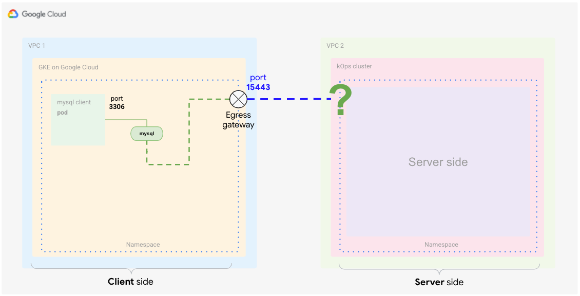
In Cloud Shell, create the following YAML file and name it
client-egress-gateway.yaml:cat <<EOF > client-egress-gateway.yaml apiVersion: networking.istio.io/v1alpha3 kind: Gateway metadata: name: istio-egressgateway-mysql spec: selector: istio: egressgateway servers: - port: number: 15443 name: tls protocol: TLS hosts: - $SERVICE_URL tls: mode: ISTIO_MUTUAL EOFApply the preceding YAML file to the client cluster:
kubectl --context ${CLIENT_CLUSTER} apply -f client-egress-gateway.yamlPay attention to the ports. You used the
defaultports here for the egress servers switch, which is15443. If you want to use a different port, you need to edit the egress gatewayserviceobject to add your custom ports.The
hostsswitch defines the endpoint, which is where the traffic should be heading.
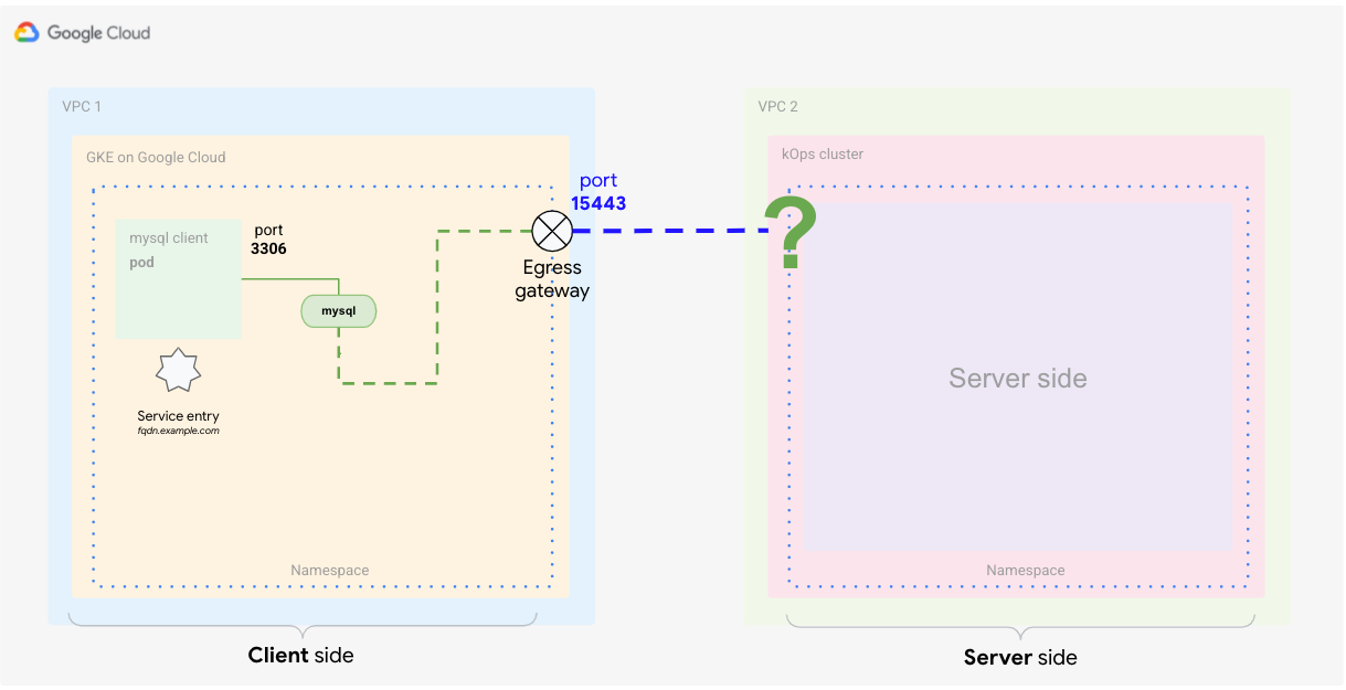
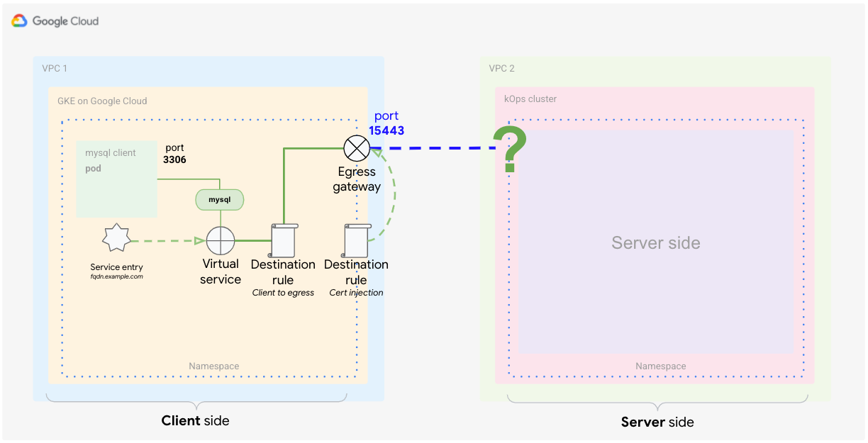
Define the service entry
The next step is to tell the service mesh about the external service. Istio has its own registry where it stores service endpoints for the mesh. If Istio is installed on top of Kubernetes, the services defined in the cluster are added to the Istio registry automatically. With the service entry definition, you add a new endpoint to the Istio registry as shown in the following diagram.
In Cloud Shell, create the following YAML file and name it
client-service-entry.yaml:cat <<EOF > client-service-entry.yaml apiVersion: networking.istio.io/v1alpha3 kind: ServiceEntry metadata: name: mysql-external spec: hosts: - $SERVICE_URL location: MESH_EXTERNAL ports: - number: 3306 name: tcp protocol: TCP - number: 13306 name: tls protocol: TLS resolution: DNS endpoints: - address: $SERVICE_URL ports: tls: 13306 EOFApply the preceding YAML file to the client cluster:
kubectl --context ${CLIENT_CLUSTER} apply -f client-service-entry.yamlThe client service definition in this YAML file tells the service what type of traffic to expect (MySQL L4 - network layer four, using port 3306). You also define that communication will go "mesh external." In the endpoints section, you define that the flow should go toward the FQDN address
$SERVICE_URLthat you set earlier and which is mapped to the ingress gateway on the server cluster (kOps).
Define the virtual service
A virtual service is a set of traffic routing rules to apply when a host is addressed. Each routing rule defines matching criteria for traffic of a specific protocol. If the traffic is matched, then it's sent to a named destination service (or a subset or version of it) defined in the registry. For more information, see the Istio documentation.
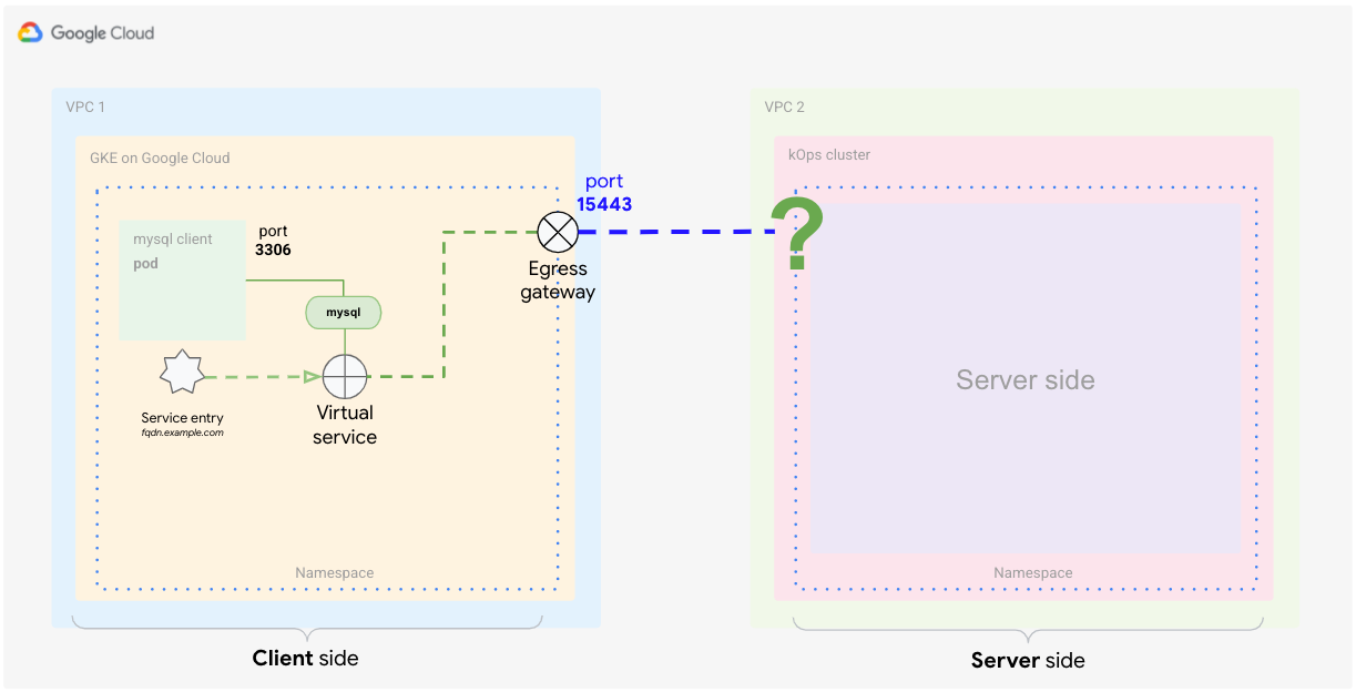
The virtual service definition tells Istio how to apply the routing for the
traffic that's reaching the external service. With the following definition, you
tell the mesh to route the traffic from the client to the egress gateway on port
15443. From the egress gateway, you then route traffic to the host
$SERVICE_URL on port 13306 (where your server-side ingress gateway is
listening).
Create the following YAML file and name it
client-virtual-service.yaml:cat <<EOF > client-virtual-service.yaml apiVersion: networking.istio.io/v1alpha3 kind: VirtualService metadata: name: direct-mysql-through-egress-gateway spec: hosts: - $SERVICE_URL gateways: - istio-egressgateway-mysql - mesh tcp: - match: - gateways: - mesh port: 3306 route: - destination: host: istio-egressgateway.istio-system.svc.cluster.local subset: mysql port: number: 15443 weight: 100 - match: - gateways: - istio-egressgateway-mysql port: 15443 route: - destination: host: $SERVICE_URL port: number: 13306 weight: 100 EOFApply the YAML definition to the client cluster:
kubectl --context ${CLIENT_CLUSTER} apply -f client-virtual-service.yamlYou can specify which gateways the configuration should apply to by editing the
gatewaysswitch in the YAML file.The important part in this definition is the use of the reserved word
mesh, which implies all the sidecars in the mesh. According to the Istio documentation, when this field is omitted, the default gateway (mesh) is used, applying the rule to all sidecars in the mesh. If you provide a list of gateway names, the rules apply only to the gateways. To apply the rules to gateways and sidecars, specifymeshas one of the gateway names.
In the next section, you define how to handle traffic that's leaving
from the client prod's proxy, match.gateways.mesh. You also define how to
route traffic from the egress to the external service by using the
match.gateways.istio-egressgateway-mysql switch.
Define a destination rule (from client to egress gateway)
Now that you've defined how to route traffic to the external service, you need to define what traffic policies should apply. The virtual service that you just defined is handling two routing cases at once. One handles traffic from the sidecar proxy to the egress gateway, and the other handles traffic from the egress gateway to the external service.
To match these cases with the destination rules, you need two separate rules. The following diagram shows the first rule, which handles traffic from the proxy to the egress gateway. In this definition, you tell Anthos Service Mesh to use its default certificates for mTLS communication.
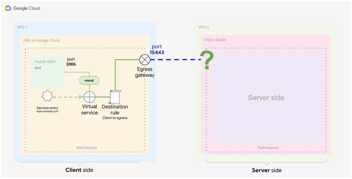
In Cloud Shell, create the following YAML file and name it
client-destination-rule-to-egress-gateway.yaml:cat <<EOF > client-destination-rule-to-egress-gateway.yaml apiVersion: networking.istio.io/v1alpha3 kind: DestinationRule metadata: name: egressgateway-for-mysql spec: host: istio-egressgateway.istio-system.svc.cluster.local subsets: - name: mysql trafficPolicy: loadBalancer: simple: ROUND_ROBIN portLevelSettings: - port: number: 15443 tls: mode: ISTIO_MUTUAL sni: $SERVICE_URL EOFApply the preceding YAML definition to the client cluster:
kubectl --context ${CLIENT_CLUSTER} apply -f client-destination-rule-to-egress-gateway.yamlIn the preceding YAML file, you used the
hostsswitch to define how to route traffic from the client proxy to the egress gateway. Also, you configured the mesh to useISTIO_MUTUALon port15443, which is one of the ports automatically open at the egress gateway.
Create a destination rule (from egress gateway to external service)
The following diagram shows the second destination rule, which tells the mesh how to handle traffic from the egress gateway to the external service.
You need to tell the mesh to use your injected certificates for mutual TLS communication with the external service.
In Cloud Shell, from the
anthos-service-mesh-samples/docs/mtls-egress-ingressdirectory, create the certificates:./create-keys.shMake sure to provide a password when the script asks for it.
Copy the generated files to the current directory:
cp ./certs/2_intermediate/certs/ca-chain.cert.pem ca-chain.cert.pem
cp ./certs/4_client/private/$SERVICE_URL.key.pem client-$SERVICE_URL.key.pem
cp ./certs/4_client/certs/$SERVICE_URL.cert.pem client-$SERVICE_URL.cert.pem
Create a Kubernetes secret that stores the certificates so that they can be referenced later in the gateway:
 kubectl --context ${CLIENT_CLUSTER} create secret -n istio-system \
  generic client-credential \
  --from-file=tls.key=client-$SERVICE_URL.key.pem \
  --from-file=tls.crt=client-$SERVICE_URL.cert.pem \
  --from-file=ca.crt=ca-chain.cert.pem
The preceding command adds the following certificate files to the secret:
client-$SERVICE_URL.key.pem
client-$SERVICE_URL.cert.pem
ca-chain.cert.pem
The current best practice of distributing certificates is followed here by using secret discovery service (SDS) instead of file mounts. This practice avoids restarting the pods when adding a new certificate. Starting with Istio 1.8/1.9, with this technique you no longer need read access rights (RBAC) for the secret of the gateways.
Add the certificates to the
DestinationRuleand name itclient-destination-rule-to-external-service.yaml:cat <<EOF > client-destination-rule-to-external-service.yaml apiVersion: networking.istio.io/v1alpha3 kind: DestinationRule metadata: name: originate-mtls-for-mysql spec: host: $SERVICE_URL trafficPolicy: loadBalancer: simple: ROUND_ROBIN portLevelSettings: - port: number: 13306 tls: mode: MUTUAL credentialName: client-credential sni: $SERVICE_URL EOFApply the preceding YAML definition to the client cluster:
kubectl --context ${CLIENT_CLUSTER} apply -f client-destination-rule-to-external-service.yamlThis rule works only if you have created the secret beforehand. The secret ensures that the certificates are used for the mTLS encryption from egress gateway to the external endpoint.
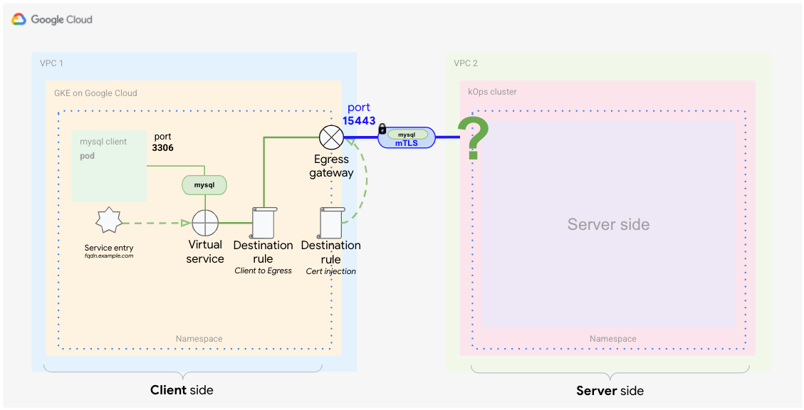
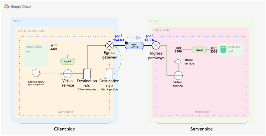
When you've completed these steps, your client side setup is done and looks like the following diagram.
Configuring the server side
As discussed in the concept guide, for the server side you need to configure the ingress gateway in Anthos Service Mesh. Before you create the necessary files, it's a good idea to review which components are required to realize the server part of the solution.
Basically, you want to identify incoming traffic based on its origin and certificate. You also want to specifically route only that traffic to its destination: your MySQL DB in a container. Typically you use a service in Kubernetes to do this, but in this example, you identify the incoming traffic inside the mesh communication, so you need a special definition of a service that includes the following:
- TLS certificates (as a secret)
- Ingress gateway
- Virtual service
Create the secret for the ingress gateway
As you did for the egress gateway, you need the same certificates to secure communication for the ingress gateway. To accomplish this, store the certificates in a secret and define this secret with your ingress gateway object.
In Cloud Shell, copy the generated files to the location you are executing the next command from:
cp ./certs/3_application/private/$SERVICE_URL.key.pem server-$SERVICE_URL.key.pem
cp ./certs/3_application/certs/$SERVICE_URL.cert.pem server-$SERVICE_URL.cert.pem
Create the server secret:
kubectl --context ${SERVER_CLUSTER} create secret -n istio-system \
    generic mysql-credential \
    --from-file=tls.key=server-$SERVICE_URL.key.pem \
    --from-file=tls.crt=server-$SERVICE_URL.cert.pem \
    --from-file=ca.crt=ca-chain.cert.pem
You just added the following certificate files to the secret:
server-$SERVICE_URL.key.pem
server-$SERVICE_URL.cert.pem
ca-chain.cert.pem
Define the ingress gateway
To receive traffic from the client-side cluster, you need to specify an ingress gateway that can decrypt and verify the TLS communication by using the certificates.
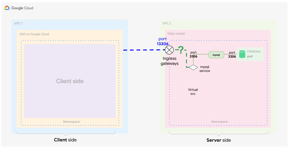
This diagram shows where the ingress gateway sits in your cluster. Traffic passes through and is inspected if it fits the security and forwarding criteria.
In Cloud Shell, use the following YAML file and name it
server-ingress-gatway.yaml:cat <<EOF > server-ingress-gatway.yaml apiVersion: networking.istio.io/v1alpha3 kind: Gateway metadata: name: gateway-mysql spec: selector: istio: ingressgateway # Istio default gateway implementation servers: - port: number: 13306 name: tls-mysql protocol: TLS tls: mode: MUTUAL credentialName: mysql-credential hosts: - "$SERVICE_URL" EOFApply the preceding YAML definition to the client cluster:
kubectl --context ${SERVER_CLUSTER} apply -f server-ingress-gatway.yamlPay attention to the
tls:section because it's especially important. In this section, you define that you want mTLS. To ensure that this works as expected, you need to provide the secret that you created which contains the certificates.Enable port
13306by patching the ingress service. You enable this port by creating the following JSON file and naming itgateway-patch.json:cat <<EOF > gateway-patch.json [{ "op": "add", "path": "/spec/ports/0", "value": { "name": "tls-mysql", "protocol": "TCP", "targetPort": 13306, "port": 13306 } }] EOFApply the patch to the gateway service:
kubectl --context ${SERVER_CLUSTER} -n istio-system patch --type=json svc istio-ingressgateway -p "$(cat gateway-patch.json)"
Now that you've opened up the port on the ingress gateway, you need to pick up traffic coming from your new ingress gateway and direct it to your database Pod. You do this by using a mesh internal object: the virtual service.
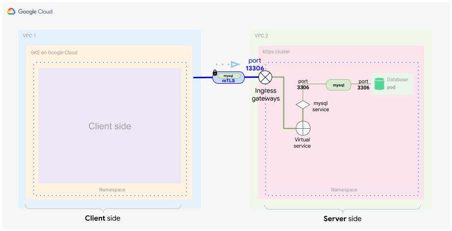
Define the virtual service
As discussed earlier, the virtual service is a definition of traffic matching patterns that shape traffic within your mesh. You need to correctly identify and forward the traffic from your ingress gateway toward your MySQL DB service, as shown in the following diagram.
In Cloud Shell, create the following YAML file and name it
server-virtual-service.yaml:cat <<EOF > server-virtual-service.yaml apiVersion: networking.istio.io/v1alpha3 kind: VirtualService metadata: name: mysql-virtual-service spec: hosts: - "$SERVICE_URL" gateways: - gateway-mysql tcp: - route: - destination: port: number: 3306 host: mysql.default.svc.cluster.local EOFIt's important that this virtual service references the ingress gateway that the traffic comes from. The gateway is named
gateway-mysql.Because this virtual service is applied on L4, you need to provide a
tcpflag to describe your MySQL traffic. This flag basically tells the mesh that L4 is used for this traffic.You might have noticed that the ingress service is using port
13306to forward traffic. The virtual service picks that up and translates it back to3306.Finally, you are forwarding traffic to the MySQL server in the server Kubernetes cluster. For this example, the server is listening on the standard MySQL port
3306.Apply the YAML definition to the server cluster:
kubectl --context ${SERVER_CLUSTER} apply -f server-virtual-service.yaml
These two definitions decrypt the mTLS-encapsulated MySQL client request and forward it to the MySQL database inside the mesh.
It's important to understand that the mesh internal forwarding is also done using encryption, but in this case, the encryption is based on mesh internal certificates. The mTLS termination happens at the gateway.
Now you have a fully and mutually encrypted way of communicating with your MySQL server. This form of encryption is transparent for the MySQL client and server, so no application changes are necessary. This makes tasks such as changing or rotating certificates straightforward. Also, this way of communication can be used for many different scenarios.
Testing the setup
Now that you have client and server sides in place, you can test the setup.
It's time to generate some traffic from the client side to the server side. You want to follow the traffic flow and ensure that the traffic is routed and encrypted and decrypted as you intend.
In Cloud Shell, deploy the MySQL server into the server cluster:
kubectl --context ${SERVER_CLUSTER} apply -f server/mysql-server/mysql.yamlStart a MySQL client on the client cluster:
kubectl run --context ${CLIENT_CLUSTER} --env=SERVICE_URL=$SERVICE_URL -it --image=mysql:5.6 mysql-client-1 --restart=Never -- /bin/bashWhen the container has started, you are presented with a shell, which should look like the following:
root@mysql-client-1:/#
Connect to your MySQL server:
mysql -pyougottoknowme -h $SERVICE_URLUse the following commands to add a DB and a table:
CREATE DATABASE test_encrypted_connection;
USE test_encrypted_connection;
CREATE TABLE message (id INT, content VARCHAR(20));
INSERT INTO message (id,content) VALUES(1,"Crypto Hi");
After connecting and adding the table, exit the MySQL connection and the Pod:
exit
exit
You need to type exit twice—first, to leave the DB connection, and second, to leave the Pod. If the Pod stops responding upon exit, press Control+C to cancel out of the bash shell.
By following these steps, you should have generated some meaningful logging output that you can now further analyze.
In the next section, you check that the client-side traffic is passing the proxy and the egress gateway. You also test whether you can see the traffic entering the server side through the ingress gateway.
Test the client-side proxy and egress gateway
In Cloud Shell, on the client side proxy, check that you can see the Istio proxy logs:
kubectl --context ${CLIENT_CLUSTER} logs -l run=mysql-client-1 -c istio-proxy -fThe debug output looks similar to the following:
[2021-02-10T21:19:08.292Z] "- - -" 0 - "-" "-" 176 115 10 - "-" "-" "-" "-" "192.168.1.4:15443" outbound|15443|mysql|istio-egressgateway.istio-system.svc.cluster.local 192.168.1.12:58614 34.66.165.46:3306 192.168.1.12:39642 - -
Press Control+C to exit the log output.
In this log entry, you can see that the client requests the server running on IP address
34.66.165.46on port3306. The request is forwarded (outbound) toistio-egressgatewaylistening on the IP address192.168.1.4port15443. You defined this forwarding in your virtual service (client-virtual-service.yaml).Read the egress gateway proxy logs:
kubectl --context ${CLIENT_CLUSTER} logs -n istio-system -l app=istio-egressgateway -fThe debug output is similar to the following:
[2021-02-10T21:19:08.292Z] "- - -" 0 - "-" "-" 176 115 19 - "-" "-" "-" "-" "34.66.165.46:13306" outbound|13306||34.66.165.46.nip.io 192.168.1.4:53542 192.168.1.4:15443 192.168.1.12:58614 34.66.165.46.nip.io -
Press Control+C to exit the log output.
In this log entry, you can see that the client request routed to
istio-egressgatewaylistening on the IP address192.168.1.4port15443is further routed to the outside the service mesh to the external service listening on the IP address34.66.165.46on port13306.You defined this forwarding in the second part of your virtual service (client-virtual-service.yaml).
Test the server-side ingress gateway
In Cloud Shell, on the server side, view the ingress gateway proxy logs:
kubectl --context ${SERVER_CLUSTER} logs -n istio-system -l app=istio-ingressgateway -fThe output in the log looks similar to the following:
[2021-02-10T21:22:27.381Z] "- - -" 0 - "-" "-" 0 78 5 - "-" "-" "-" "-" "100.96.4.8:3306" outbound|3306||mysql.default.svc.cluster.local 100.96.1.3:55730 100.96.1.3:13306 100.96.1.1:42244 34.66.165.46.nip.io -
Press Control+C to exit the log output.
In this log entry, you can see that the external client request routed to
istio-ingressgatewaylistening on the IP address34.66.165.46port13306is further routed to the MySQL service inside the mesh identified by the service namemysql.default.svc.cluster.localon port3306.You defined this forwarding in the ingress gateway (server-ingress-gateway.yaml).For the MySQL server, view the Istio proxy logs:
kubectl --context ${SERVER_CLUSTER} logs -l app=mysql -c istio-proxy -fThe output looks similar to the following:
[2021-02-10T21:22:27.382Z] "- - -" 0 - "-" "-" 1555 1471 4 - "-" "-" "-" "-" "127.0.0.1:3306" inbound|3306|mysql|mysql.default.svc.cluster.local 127.0.0.1:45894 100.96.4.8:3306 100.96.1.3:55730 outbound_.3306_._.mysql.default.svc.cluster.local -
Press Control+C to exit the log output.
In this log entry, you can see the inbound call to the MySQL database server listening on the IP address
100.96.4.8port3306. The call is coming from the ingress Pod with the IP address100.96.1.3.For more information about the Envoy logging format, see Getting Envoy's Access Logs.
Test your database to see the generated input:
MYSQL=$(kubectl --context ${SERVER_CLUSTER} get pods -n default | tail -n 1 | awk '{print $1}')
kubectl --context ${SERVER_CLUSTER} exec $MYSQL -ti -- /bin/bash
Verify the created database:
mysql -pyougottoknowme
USE test_encrypted_connection;
SELECT * from message;
The output is similar to the following:
+------+-----------+
| id   | content   |
+------+-----------+
|    1 | Crypto Hi |
+------+-----------+
1 row in set (0.00 sec)
Leave the MySQL database:
exit
exit
You need to type
exittwice—first, to leave the DB connection, and second, to leave the Pod.
Test access by omitting the certificates
Now that you have tested and verified that access works using the injected certificates, also test the opposite: what happens if you omit the egress gateway and the certificate injection. This testing is also called negative testing.
You can perform this test by launching another Pod in a namespace without side proxy injection enabled.
In Cloud Shell, create a new namespace:
kubectl --context ${CLIENT_CLUSTER} create ns unencryptedCreate a Pod and start an interactive shell inside the container:
kubectl --context ${CLIENT_CLUSTER} run -it --image=mysql:5.6 \
mysql-client-2 --env=SERVICE_URL=$SERVICE_URL \
-n unencrypted --restart=Never -- /bin/bash
Try to connect to the database once the interactive shell has started:
mysql -pyougottoknowme -h $SERVICE_URLAfter 30 seconds, you see output similar to the following:
Warning: Using a password on the command line interface can be insecure.
ERROR 2003 (HY000): Can't connect to MySQL server on '104.154.164.12.nip.io' (110)
This warning is expected because this Pod is omitting the egress gateway and trying to reach the ingress gateway (the
$SERVICE_URL) directly through the internet.Try to resolve the service IP address:
resolveip $SERVICE_URLThe output is similar to the following. Your IP address will be different.
IP address of 104.154.164.12.nip.io is 104.154.164.12
This proves that the FQDN is resolvable and that the failed connection is indeed due to the missing certificate injection.
Exit the MySQL connection and the MySQL server Pod:
exit
exit
Further investigation
One topic not covered in this tutorial is that typically egress configurations are
owned by a different role or organization in your company, because they are
hosted in the istio-system namespace. Configure Kubernetes RBAC permissions so
that only network administrators can directly create and modify the resources
discussed in this tutorial.
Now that you know how to use a service mesh to help ensure secure communication, you might want to try it with an application that needs to securely exchange data and where you want to control the encryption down to the certificate layer. To get started, you can install Anthos Service Mesh.
Try using two GKE clusters and combine them by using the technique in this tutorial. This technique also works in the GKE Enterprise platform between two foreign Kubernetes clusters.
Service meshes are an excellent way to increase security within your cluster as well as with external services. One final use case to try is to have a mTLS endpoint that is not a second Kubernetes cluster but a third-party provider (such as a payment provider).
Clean up
To avoid incurring charges to your Google Cloud account for the resources used in this tutorial, you can delete your project.
Delete the project
- In the Google Cloud console, go to the Manage resources page.
- In the project list, select the project that you want to delete, and then click Delete.
- In the dialog, type the project ID, and then click Shut down to delete the project.
What's next
- Read the companion concept guide.
- For further best practices on configuring your egress gateway, see Using Anthos Service Mesh egress gateways on GKE clusters: Tutorial.
- Consult the GKE hardening guide and the accompanying Terraform module.
- Explore reference architectures, diagrams, and best practices about Google Cloud. Take a look at our Cloud Architecture Center.