This document shows network, platform, and security engineers who administer Kubernetes clusters how to handle external, cluster-to-cluster communication by using Anthos Service Mesh ingress and egress gateways. The document describes how to use Anthos Service Mesh to encrypt and help secure outbound traffic (egress) from workloads deployed on one Kubernetes cluster to workloads running in another Kubernetes cluster. The techniques described show how to use separate certificates for mutual, encrypted, cluster-to-cluster communication.
The guidance in this document stems from customer requirements to use a specific root Certificate Authority (CA) for intra-cluster communication. You might find such requirements in highly regulated markets, such as financial services or healthcare. The guidance presented here also allows the use of endpoints other than Kubernetes clusters, such as financial clearance providers or an API interface for sensitive data. This guidance is especially relevant for organizations who need to adhere to strict security and auditing policies.
You can operate and handle the encrypted communication without touching the workloads running in the clusters. For guidance on how to configure your own clusters, follow the accompanying tutorial.
Introduction
When enterprises first start adopting Kubernetes, they often start with a single cluster, where most communication stays within that cluster. Soon, cross-namespace interaction becomes increasingly important, which is where a network policy provider such as Calico or Cilium can help. However, as container environments grow it becomes more relevant to ensure that communication can happen securely between external services and your containers that are running inside Kubernetes clusters.
Network policy is a great way to deal with traditional security concepts such as creating cluster-internal firewall rules, but it has only limited use outside of the cluster. It's possible to allow only a specific IP address to be reached, but no control over the content or identity is available. Therefore, a more versatile concept is required, which also helps you encrypt traffic to other external services. The following diagram offers one approach.

In the world of applications, encryption is usually done by using TLS (Transport Layer Security). This means you can encrypt traffic by using a private (secret) certificate with a public counterpart, as shown in the preceding diagram. The receiving party holds the public certificate, which is used to verify that the information is coming from a trusted source. HTTPS web traffic uses TLS to help ensure secure and encrypted communications between a client and a web server. In this case, the public certificate comes from a trusted issuer (like Google Trust Services), also referred to as a CA, that is part of the public key infrastructure (PKI). TLS verifies the identity of the server, but it doesn't verify the identity of the client.
In cases where the client itself must also be verified, mutual authentication, or mTLS, is required. mTLS is used when both the sender and receiver must identify themselves to the other party, as shown in the following diagram.
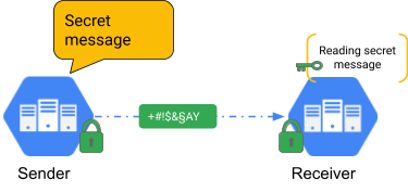
This method is often used for applications that need an extra layer of security. In the financial industry, and for personally identifiable information (PII), regulators often require mTLS.
Anthos Service Mesh
Anthos Service Mesh is a Google-managed service mesh solution based on OSS Istio. That means that it is 100% Istio API compatible. Anthos Service Mesh can provide mTLS functionality at the platform level instead of inside the application code, which means it can apply to services without requiring you to recode every service. Operations like certificate rotation are also part of Anthos Service Mesh. This document focuses on mTLS and the external communication features of Anthos Service Mesh. There are many other features such as fault injection, advanced load balancing, and error handling.
By routing all traffic through side-car proxies (Envoy), service meshes such as Anthos Service Mesh unburden the developer from mundane (but important) tasks such as encryption and certificate handling. By using a transparent proxy, service meshes can enable powerful L7 functions such as routing HTTP and HTTPS calls based on header information. However, Anthos Service Mesh also enables traffic encapsulation and encryption, which can help improve security.
Example configuration: MySQL communication between clusters
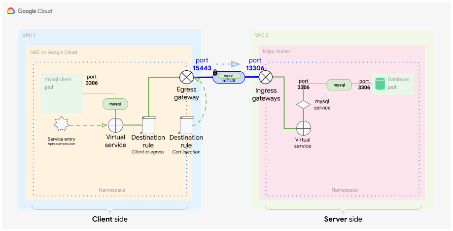
You can use this scenario when you want to have secure and trusted communication between services in different clusters. In this example, the MySQL client application is talking to a MySQL server DB workload running in a different Kubernetes cluster, as the following diagram shows.
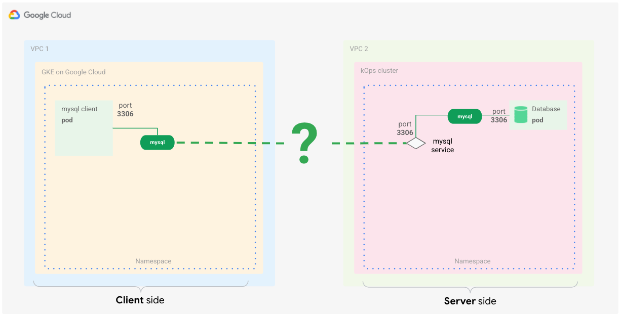
Although service meshes often work at OSI L7, you can also use some of their functionality to control L4 communications.
Here's what you need in order to make the concept work:
- The communication between applications and clusters must be encrypted.
- The client and server communication need to be mutually verified (mTLS).
- The client and server workloads don't need to change.
Although you can set up the MySQL database to accept only encrypted connections, that setup requires you to change the database client, which you might not have full control over.
There are multiple ways to address these requirements by using Anthos Service Mesh. One way is to create a shared Istio control plane between clusters and have the services communicate with each other because they belong to a single logical service mesh. You can do this for Anthos-enabled GKE clusters by using Anthos Service Mesh either in a single project or multi-project setup.
However, because there's a requirement to have a separate trust chain for cluster-to-cluster communication you can use the egress gateway <–> ingress gateway approach using mTLS.
Egress and ingress gateways are Envoy proxies that live on the boundaries of the mesh.
You can configure them to control traffic flow into and out of the service mesh.This also works for non-Kubernetes endpoints and lets you use different certs for the encrypted communication.
Configure Anthos Service Mesh egress and ingress
In the preceding scenario, you handle secure, cluster-to-cluster communication by using egress and ingress gateways between the respective clusters.
What is an egress gateway?
Egress means traffic that's flowing out of your service mesh. An egress gateway provides a controlled exit point for that traffic.
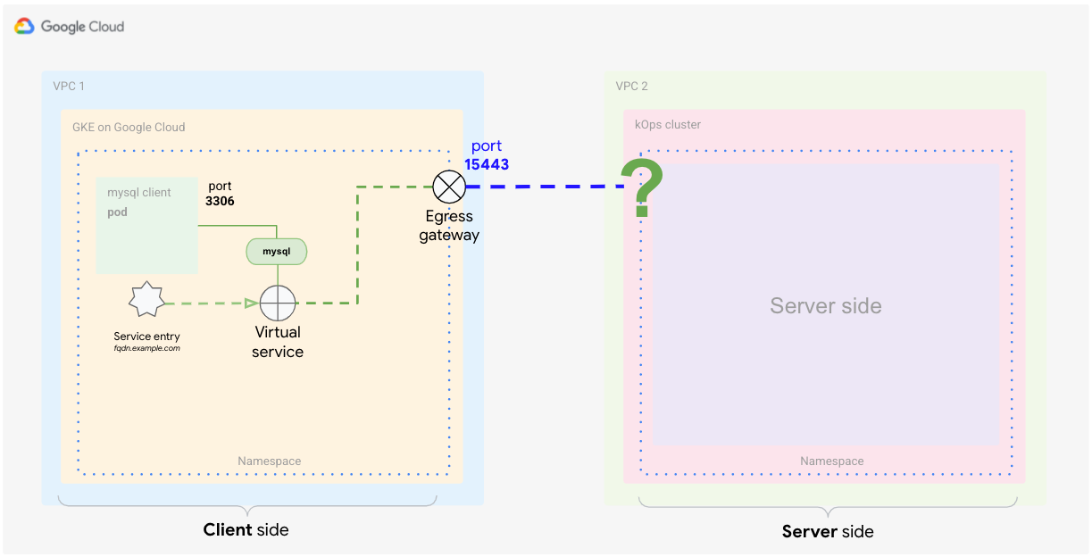
Without additional configuration, for a Pod where the sidecar proxy has been injected, traffic destined for a service that resides outside of the mesh (for example, a public API service) is routed from the Pod to the sidecar proxy. In a GKE cluster (and most other Kubernetes clusters), the Node IP address uses a NAT to translate sidecar proxy traffic, which flows directly to the external address of the service. The following diagram shows this configuration.
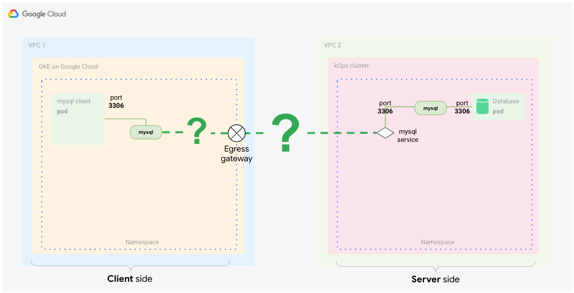
In this diagram, the client is calling the server side, which represents the external service. To the mesh, this traffic is outbound, so you need to configure the egress gateway on the client side (for example, the MySQL client).
You configure the egress gateway to forward the call to the external service. After the external service processes the request and returns the response, it again goes through the egress gateway back to the client proxy and finally to the Pod that's issuing the call (for example, the MySQL client).
What is an ingress gateway?
Ingress means traffic that's flowing into the service mesh. An ingress gateway exposes services to the outside world (that is, outside the service mesh) and handles how these services should be accessible. It's comparable to a Kubernetes Ingress object.
With an ingress gateway, you can define a single controlled entrypoint where traffic goes into the mesh. Initially, the traffic enters through the load balancer, which is created by defining an ingress gateway service. From there, the request is forwarded to the sidecar proxy, and from the proxy it is forwarded to the Pod. The Pod can process the request and return the response by using the same route in reverse. The following diagram shows this configuration.
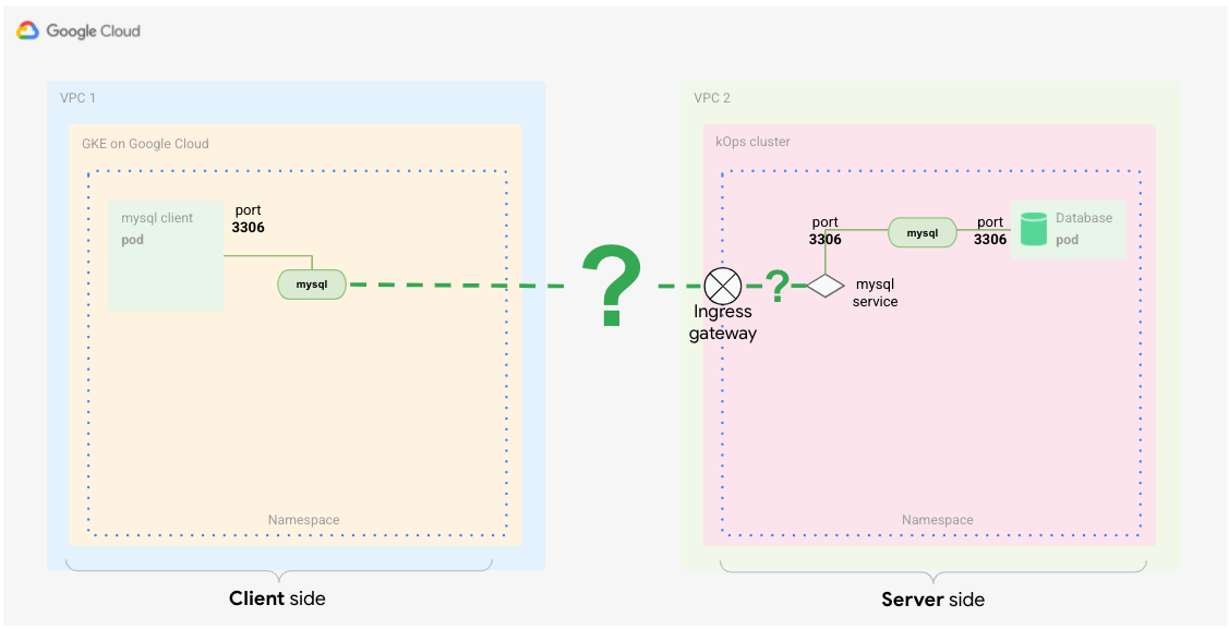
This traffic is inbound traffic to the mesh of the other cluster (VPC 2). Therefore, you need to configure the ingress gateway on the server side to handle those calls.
The server-side configuration of the ingress gateway forwards the call to the internal service. After the internal service processes the request, the response it returns traverses back through the ingress gateway to the client.
Combining egress and ingress functionality for mutual TLS
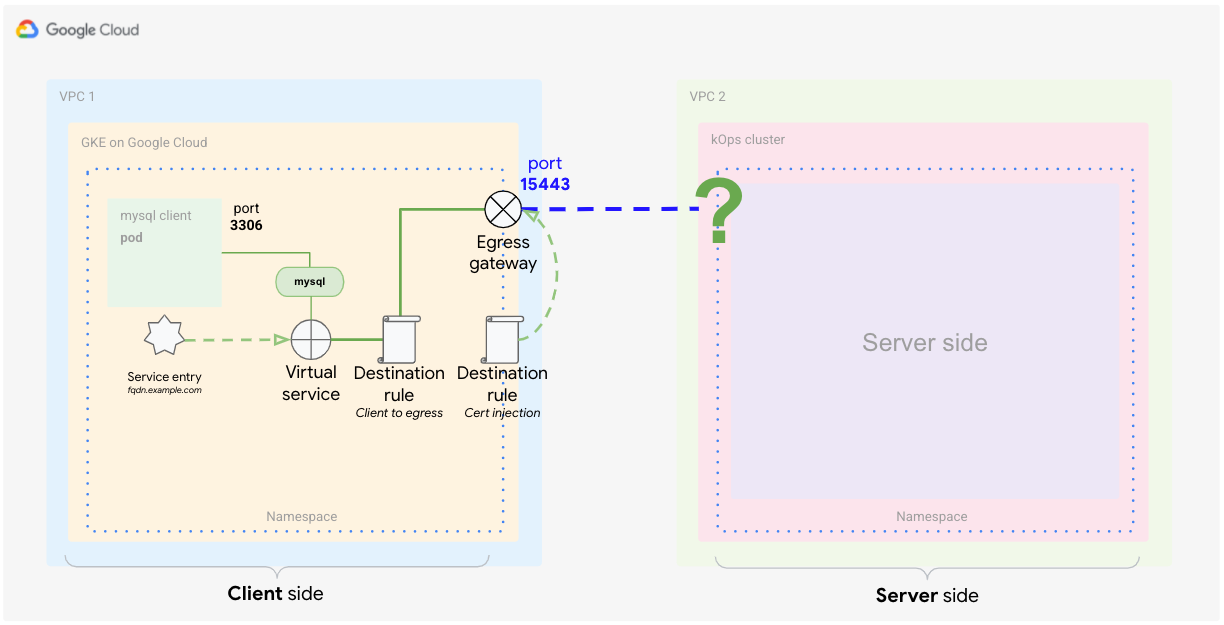
As mentioned previously, for the client side you need to define an egress gateway that acts as a controlled exit point for the service mesh. To make sure that traffic leaving the mesh through the gateway is encrypted by mTLS, you can use a technique called TLS origination. Configure an egress gateway to perform TLS origination for traffic to external services.
When the traffic leaving the service mesh from the client side is encrypted, you need to make sure the server side can identify itself to the client and decipher the encrypted traffic.
For that you use the ingress gateway as a single point of entry into the mesh. Configure the ingress gateway so that it expects mutually encrypted traffic.
Mesh architecture overview
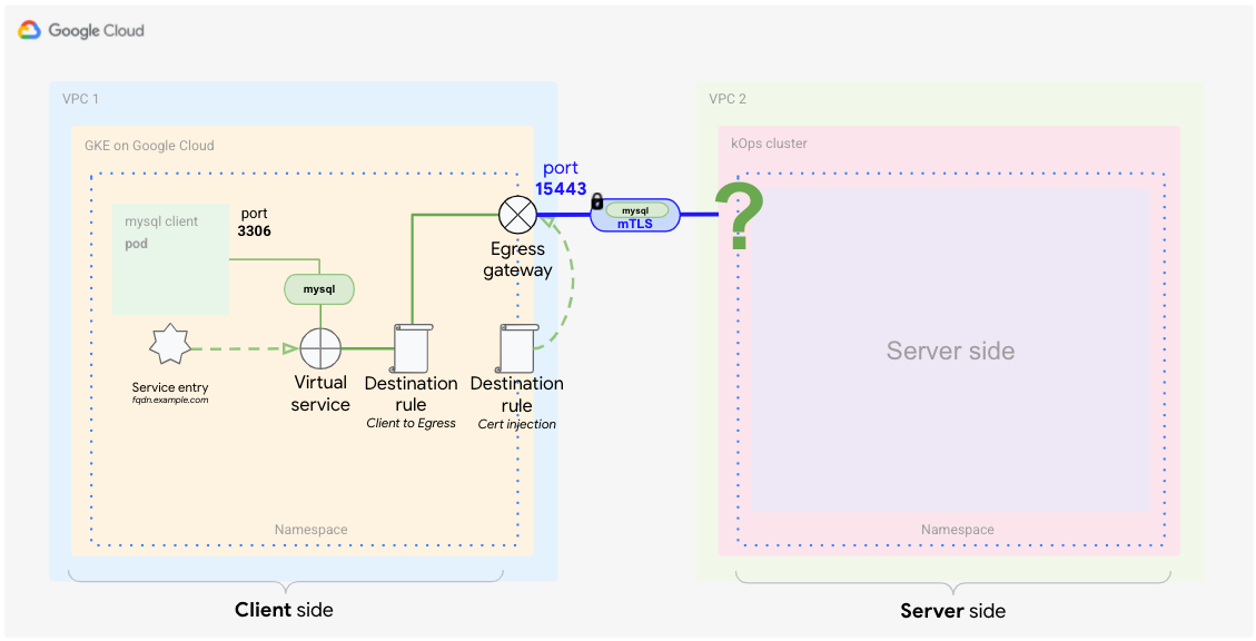
The following diagram describes what's necessary to implement this concept for the MySQL scenario, without changing anything in the application or the server.
In VPC 1, you see that the client cluster running MySQL client is accessing the server. The server is located in VPC 2.
The client side is more configuration heavy than the server side because you need to do a bit more traffic matching and routing, to ensure that the application uses the egress gateway. However, this configuration is a day-zero effort, meaning you have to do it only once. Once you implement it, it's fairly easy to maintain.
A benefit of implementing this concept using Kubernetes is that all configuration items are stored in YAML files. This means the entire construct can be used on a versioned repository, which lets you track changes and easily revert them if necessary.
The client side
This subsection examines the client-side configuration. Each element you see in the diagram has a distinct function in the mesh to control how the traffic is routed through the egress gateway to reach its destination, the MySQL server.
Traffic routing is only one part of the required functionality. Other elements control the encryption of the traffic, fully transparent, to help ensure that the communication is always secure. The following sections examine the elements to further understand their role and function in this scenario.
Service entry
A service mesh creates its own service registry to a Kubernetes cluster. The control plane uses this registry to configure the side-car proxies as a routing table. The services running in Kubernetes are automatically discovered and added to the service mesh registry. Services not running inside the Kubernetes cluster cannot be automatically discovered, but can be defined by using ServiceEntries. This way, the client can use an entry as a hostname to connect to external services.
In Anthos Service Mesh, fully qualified domain names (FQDNs) are used to identify all services. The FQDN is the most important part in this construct because the certificates are based on the hostname. Although it's possible to change the FQDN, it means that you also need to regenerate all necessary certificates.
To enable communication, you must configure the service mesh to listen for calls toward the external service in order to properly route the traffic. The mesh lets you define a service entry that points to that external service.
This construct is called MESH_EXTERNAL and is ideal for these use cases. You
might also want to specify what you're looking for. Because this is an L4 use
case and you can only control the IP address and port, you need to tell the mesh
the protocol and the specific ports—in this case, TCP and port 3306 (the
standard MySQL protocol port). Also, the server-side counterpart (as shown in
the preceding diagram) is listening on port 13306 (the egress gateway of the
server cluster). Finally, you need to tell your service entry to capture traffic
with this port tag.
The following example YAML service entry illustrates this configuration:
apiVersion: networking.istio.io/v1alpha3
kind: ServiceEntry
metadata:
 name: mysql-external
spec:
 hosts:
   - mysql.fqdn.example
 location: MESH_EXTERNAL
 ports:
   - number: 3306
     name: tcp
     protocol: TCP
   - number: 13306
     name: tls
     protocol: TLS
 resolution: DNS
 endpoints:
   - address: mysql.fqdn.example
     ports:
       tls: 13306
With the hosts field, you can set the FQDN of the external service, or you
can specify the location field to be MESH_EXTERNAL. You must also specify
the ports values used by the external service—in this case, 13306 and
3306.
13306 will be the exposed port from the server-side ingress gateway. It's
important to specify both in this service entry. For the protocol, you must
specify TLS, because this connection provides L4-based TLS communication.
When you have defined the service entry, the mesh can then listen for calls and change the routing based on these rules.
Service entries must be based on existing DNS or IP address entries, meaning
that the DNS name should already be resolvable by a DNS server. For example, you
can use a core DNS service inside Kubernetes and add entries to it that are not
already present in kube-dns. You can't use the service entry to create a DNS
entry.
Virtual service
The virtual service is a definition used to affect traffic routing patterns. You use the virtual service to make sure that calls from the MySQL client to the service entry are routed to the egress gateway. Thus, you can set up a virtual service to route traffic based on vastly different factors. In an L7 use case, these factors go beyond traffic routing. For example, you can tell the virtual service how to react if a target is unreachable. This example uses a subset of this functionality in order to route matching traffic only to the egress gateway for further processing.
The preceding diagram shows how you use the virtual service to route traffic from the Pod through the proxy to the egress gateway and from the egress gateway to the external service.
You must also specify the port of your egress gateway (externally facing),
which is 15443 by default. This port is set on the egress gateway once you
create it. You can pick any other free port, but you'd need to patch the gateway
to open the chosen port.
The following code snippet shows what such a virtual service definition might look like:
apiVersion: networking.istio.io/v1alpha3
kind: VirtualService
metadata:
 name: direct-mysql-through-egress-gateway
spec:
 hosts:
   - mysql.fqdn.example
 gateways:
   - istio-egressgateway-mysql
   - mesh
 tcp:
   - match:
       - gateways:
           - mesh
         port: 3306
     route:
       - destination:
           host: istio-egressgateway.istio-system.svc.cluster.local
           subset: mysql
           port:
             number: 15443
         weight: 100
   - match:
       - gateways:
           - istio-egressgateway-mysql
         port: 15443
     route:
       - destination:
           host: mysql.fqdn.example
           port:
             number: 13306
         weight: 100
The hosts field holding the FQDN URL is used to apply the match rules
specifically on the given URL. The first match clause is defined on the mesh,
which is a reserved keyword and applies to all gateways within the mesh. The
first route block is defined to tell the mesh what to do if the match is true.
In this case, you send the matched traffic to the egress gateway. This is where the
egress port is defined in addition to the weighting for the route. The block
also mentions a subset value, which you define later.
The second match clause is applied to the egress gateway. The
second route block appended to the second match clause configures the mesh
to send the traffic to the server cluster ingress by using the host field
with the ingress FQDN and by specifying port 13306.
For the next step, you must program the certificate injection into the gateway for the mTLS communication to work.
Destination rules
Now that you have your traffic properly identified (service entry) and routed from the Pod through the proxy to the gateway (virtual service) the next step is encrypting the traffic. You use destination rules to encrypt the traffic. Such rules in a service mesh are applied to the traffic after the routing and are used to introduce load balancing and other traffic management functionality.
In this case, you use destination rules to define a standard load balancing pattern and also to add certificates to enable endpoints using mTLS communication. This step is performed by matching the FQDN of the MySQL server, exposed through the server cluster's ingress gateway, and defining an mTLS rule.
The following definition is an example of such a destination rule:
apiVersion: networking.istio.io/v1alpha3
kind: DestinationRule
metadata:
  name: egressgateway-for-mysql
spec:
  host: istio-egressgateway.istio-system.svc.cluster.local
  subsets:
    - name: mysql
      trafficPolicy:
        loadBalancer:
          simple: ROUND_ROBIN
        portLevelSettings:
          - port:
              number: 15443
            tls:
              mode: ISTIO_MUTUAL
              sni: mysql.fqdn.example
The host field is set to the cluster FQDN of the egress gateway. The first
destination rule is performing the inner mesh encryption of the traffic, using
the
ISTIO_MUTUAL
mode (using the FQDN of the egress gateway). In the code snippet, you define a
subset,
which is used to create round-robin load balancing and to set (overwrite) the
port to 15443. The egress gateway uses this port to send the traffic.
It's important that you set the tls field correctly because it defines the
inner mesh policy (ISTIO_MUTUAL). Under the sni (Service Name Indication)
field, you add the FQDN of the ingress gateway from your server cluster.
The second destination rule encrypts the traffic with the custom provided root CA certificates, before sending them through the egress gateway:
apiVersion: networking.istio.io/v1alpha3
kind: DestinationRule
metadata:
 name: originate-mtls-for-mysql
spec:
 host: mysql.fqdn.example
 trafficPolicy:
   loadBalancer:
     simple: ROUND_ROBIN
   portLevelSettings:
   - port:
       number: 13306
     tls:
       mode: MUTUAL
       credentialName: client-credential
       sni: mysql.fqdn.example
The host field is set again to the external FQDN. The trafficPolicy field
sets the load balancer mode to ROUND_ROBIN. It also sets the port to 13306
and the tls mode to
MUTUAL,
because now you are using the custom root CA certificates and the
counterpart—the ingress gateway also using tls MUTUAL—must identify itself
using the same signed root CA certificates. Using this port, the traffic can
flow through the server cluster by way of its ingress gateway to reach the MySQL
database.
The encryption using the custom root CA certificates is typically
done through the Envoy Secret Discovery Service (SDS)
by using a secret in Kubernetes that holds the certificates. You add the secret
name to the destination rule by using the credentialName field.
In summary, traffic now does the following:
- It's issued by MySQL transparently toward an external FQDN. This FQDN exists in mesh registration.
- It's encrypted by using a destination rule using internal mesh certificates.
- It's routed to the gateway by a virtual service.
- It's encrypted using a custom root CA by a destination rule (this is different from the mesh CA used for mesh certificates).
- It's forwarded through the egress gateway in mTLS mode.
The server side
In this scenario, the server side is easier to configure than the client side. All it requires is an ingress gateway and a virtual service entry to route the traffic to the MySQL DB server, as shown in the following diagram.
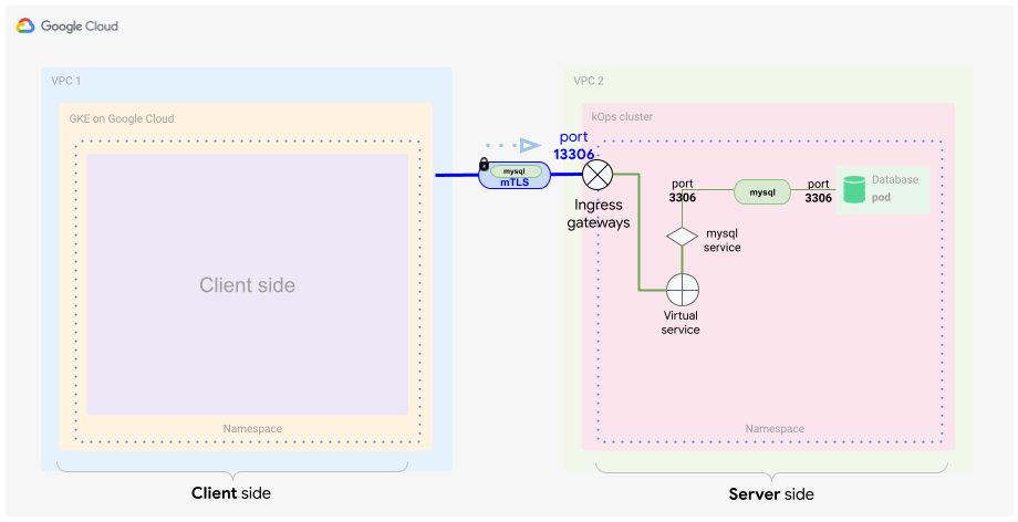
The server cluster ingress gateway
The ingress gateway is exposing port 13306. It can be any port, but in this
case it's adding a "1" in front of the standard MySQL port for easier
identification. For security reasons, we don't recommend exposing the standard
MySQL port (3306) directly to the internet.
Because the default Istio ingress gateway isn't listening on port 13306, you
need to add this functionality. The following example code snippet patches port
13306 to the gateway:
[{
  "op": "add",
  "path": "/spec/ports/0",
  "value": {
    "name": "tls-mysql",
    "protocol": "TCP",
    "targetPort": 13306,
    "port": 13306
  }
}]
You can store this code in a JSON file and use it with the kubectl patch
command to apply it to the ingress gateway service.
In order to process traffic correctly, the ingress gateway has to be set up in
MUTUAL
mode.
At this point, the ingress gateway decrypts the incoming traffic by using the certificate from its credentials store and sends the traffic into the mesh, where the mesh internal certs are used to re-encrypt the traffic. The following example code snippet shows how this might be configured:
apiVersion: networking.istio.io/v1alpha3
kind: Gateway
metadata:
 name: gateway-mysql
spec:
 selector:
   istio: ingressgateway # Istio default gateway implementation
 servers:
 - port:
     number: 13306
     name: tls-mysql
     protocol: TLS
   tls:
     mode: MUTUAL
     credentialName: mysql-credential
   hosts:
   - "mysql.fqdn.example"
In this example the standard Istio ingress gateway is used under the
selector field. Using the servers field, you can set the port
number (13306) and protocol (TLS) values that the ingress should expect.
It's important to give the port a unique name.
Define tls and provide a secret containing the certificate signed by the
same root CA as used with the egress gateway using the credentialName field.
The certificate must be stored in a Kubernetes secret.
Finally you want to match traffic directing the MySQL DB FQDN. The name
resolution for this FQDN set under hosts must be set to the ingress
gateway's public IP address.
The server cluster virtual service
After the traffic has entered the mesh through port 13306, coming from the
egress gateway of the client cluster (originator), you have to identify this
traffic and make sure it reaches the MySQL DB server. You do this by defining a
virtual service:
apiVersion: networking.istio.io/v1alpha3
kind: VirtualService
metadata:
 name: mysql-virtual-service
spec:
 hosts:
   - "mysql.fqdn.example"
 gateways:
   - gateway-mysql
 tcp:
   - route:
     - destination:
         port:
           number: 3306
         host: mysql.default.svc.cluster.local
To send the traffic to the MySQL DB service, you need to check for the FQDN
host again by using the hosts field. Also, you must use the gateways
field to configure where to apply this virtual service definition. This is the
gateway object that you defined in the preceding YAML file. Set the tcp
field, because this is L4 traffic, and set the route field to point to the
MySQL DB Kubernetes service. You must specify the service name under the host
field by using the Kubernetes cluster internal FQDN.
The MySQL DB can get requests from the client on port 3306. The traffic
traverses through the sidecar proxy of the MySQL DB server. For the MySQL DB
server it looks like a local, unencrypted request to access the database.
After the server answers the call, the traffic flows back to the client using the same route and for the client this looks as if a local DB just answered its call.
Traffic is encrypted three times using different certificates traversing from client to server which helps secure the client-server communication.
The first time the traffic is encrypted or decrypted is inside the mesh at the client side with certificates using the mesh CA.
The second time the traffic is encrypted when leaving the mesh at the egress gateway using a certificate from a custom root CA. Then the traffic is authenticated and decrypted on the ingress gateway using a certificate signed by the same custom root CA.
The last (third) time the traffic is encrypted or decrypted inside the mesh at the server side when traversing from the ingress gateway to the MySQL server. Again here (because it's mesh internal) the certificates of the mesh CA are used.
In this scenario - the communication between the two clusters had to be encrypted using the mentioned root CA. By applying this configuration, it is possible to handle this part separately and independently from the mesh internal certificates and from the application itself.
By having this extra step, this configuration also lets you easily rotate these certificates regularly without changing the mesh CA of the respective Kubernetes clusters.
What's next
- Try out the companion tutorial.
- Consult the GKE hardening guide.
- Learn about managing configuration and policy across all of your infrastructure with Config Management.
- Explore reference architectures, diagrams, and best practices about Google Cloud. Take a look at our Cloud Architecture Center.